Method and electronic equipment for regeneration control of vehicle engine particle catcher

A particle trap, regeneration control technology, applied in mechanical equipment, engine components, machines/engines, etc., can solve problems such as engine performance and life impact, and achieve the effect of extending engine life and improving performance

Pending Publication Date: 2022-06-24
GREAT WALL MOTOR CO LTD
View PDF7 Cites 0 Cited by
  • Summary
  • Abstract
  • Description
  • Claims
  • Application Information

AI Technical Summary

Problems solved by technology

[0005] In view of this, an embodiment of the present invention provides a method and electronic equipment for regeneration control of a vehicle engine p

Method used


Image

  • Method and electronic equipment for regeneration control of vehicle engine particle catcher
  • Method and electronic equipment for regeneration control of vehicle engine particle catcher
  • Method and electronic equipment for regeneration control of vehicle engine particle catcher

Examples


Example Embodiment

[0046] In the following description, for the purpose of illustration rather than limitation, specific details such as specific system structures and technologies are set forth in order to provide a thorough understanding of the embodiments of the present invention. However, it will be apparent to those skilled in the art that the present invention may be practiced in other embodiments without these specific details. In other instances, detailed descriptions of well-known systems, devices, circuits, and methods are omitted so as not to obscure the description of the present invention with unnecessary detail.

[0047] In order to illustrate the technical solutions of the present invention, the following specific embodiments are used for description.

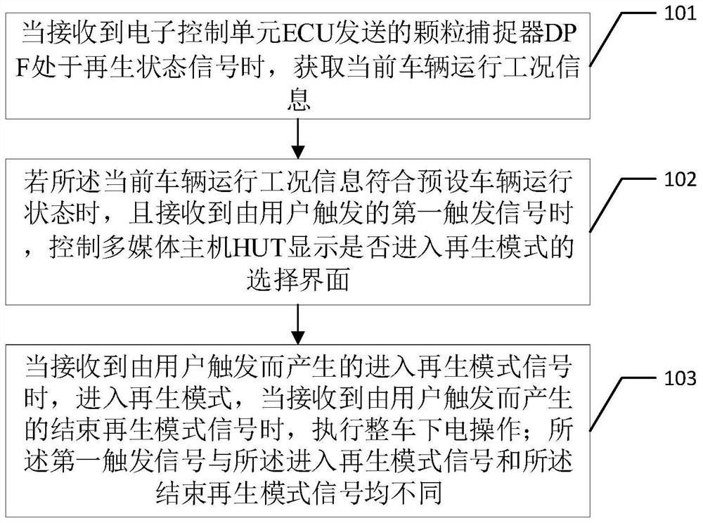
[0048] figure 1 A schematic diagram of an implementation flow of a method for regeneration control of a vehicle engine particle trap provided by an embodiment of the present invention is described in detail as follows.

[0049] S...


PUM


Abstract

The invention is suitable for the technical field of automobile control, and provides a regeneration control method for a vehicle engine particle catcher and electronic equipment, and the method comprises the steps that when a signal, sent by an ECU, that a DPF is in a regeneration state is received, current vehicle operation condition information is obtained; if the current vehicle operation condition information accords with the preset vehicle operation state and a first trigger signal triggered by a user is received, controlling a multimedia host HUT to display a selection interface whether to enter a regeneration mode or not; when a regeneration mode entering signal generated by triggering of a user is received, a regeneration mode is entered, and when a regeneration mode ending signal generated by triggering of the user is received, the whole vehicle power-off operation is executed, so that the user can participate in the regeneration process, and the user experience is improved. Therefore, the problem that the service life of an engine is affected due to the fact that a client triggers a one-key switch to interrupt DPF regeneration is solved, the service life of the engine is prolonged, and the performance of the engine can be improved by controlling a DPF regeneration mode.

Description

technical field [0001] The invention belongs to the technical field of automobile control, and in particular relates to a method and an electronic device for regeneration control of a particle trap of a vehicle engine. Background technique [0002] In the combustion chamber of the diesel engine of the vehicle, due to the diffusion combustion method of diesel injection and combustion, the formed fuel mixture is not uniform, and the excess air is prone to produce nitrogen oxides (NOx) under the action of high temperature. X ), so the exhaust gas from diesel engines contains particulate matter and nitrogen oxides. As more and more black smoke (carbon particles) are collected in the Diesel Particulate Filter (DPF), the exhaust back pressure will be too high and the power of the engine will be affected. The process in which the smoke is burned by heating the exhaust gas is called regeneration, and the regenerated filter element can be kept unobstructed without affecting the perf...

Claims


Application Information

Patent Timeline
IPC IPC(8): F01N9/00
CPCF01N9/002Y02T10/40
Inventor 李哲
Owner GREAT WALL MOTOR CO LTD
Why Eureka
Try Eureka