Welding wire air blowing device

An air intake device and air blowing technology, which are applied in the directions of drying gas arrangement, cleaning method using gas flow, progressive dryer, etc. requirements and other issues, to achieve the effect of improving the copper plating speed and removing the effect.

Active Publication Date: 2022-06-24
德州市立尊焊丝有限公司
View PDF10 Cites 0 Cited by
  • Summary
  • Abstract
  • Description
  • Claims
  • Application Information

AI Technical Summary

Problems solved by technology

[0002] Since the surface of the welding wire will produce small unevenness, the friction will increase during use, which will affect the quality of the product; the existing technology generally uses the welding wire copper plating technology, which can not only lubricate the welding wire, but also play a role in the welding wire. Anti-rust, conductive and reduces wear on wire feed contact tips
[0003] In the solid wire copper plating process, in order to ensure the surface quality of the wire, each process needs to remove the liquid brought by the previous process, so the removal speed of the liquid on the wire surface also determines the copper plating speed of the wire, with the copper plating speed The current air blowing method cannot meet the requirements of removing the liquid on the surface of the welding wire, which seriously restricts the increase in the production speed of the welding wire

Method used


Image

  • Welding wire air blowing device
  • Welding wire air blowing device

Examples


Embodiment Construction

[0020] The technical solutions in the embodiments of the present invention will be clearly and completely described below with reference to the drawings in the embodiments of the present invention. Obviously, the described embodiments are only a part of the embodiments of the present invention, but not all of the embodiments. Based on the embodiments of the present invention, all other embodiments obtained by those of ordinary skill in the art without creative efforts shall fall within the protection scope of the present invention.

[0021] It should be noted that the azimuth terms such as left, right, top, bottom, front, and back in the embodiments of the present invention are only relative concepts to each other or refer to the normal use state of the product, that is, the traveling direction of the product. and should not be considered limiting.

[0022] In addition, it should be noted that the dynamic terms such as "relative motion" mentioned in the embodiments of the pres...


PUM


Abstract

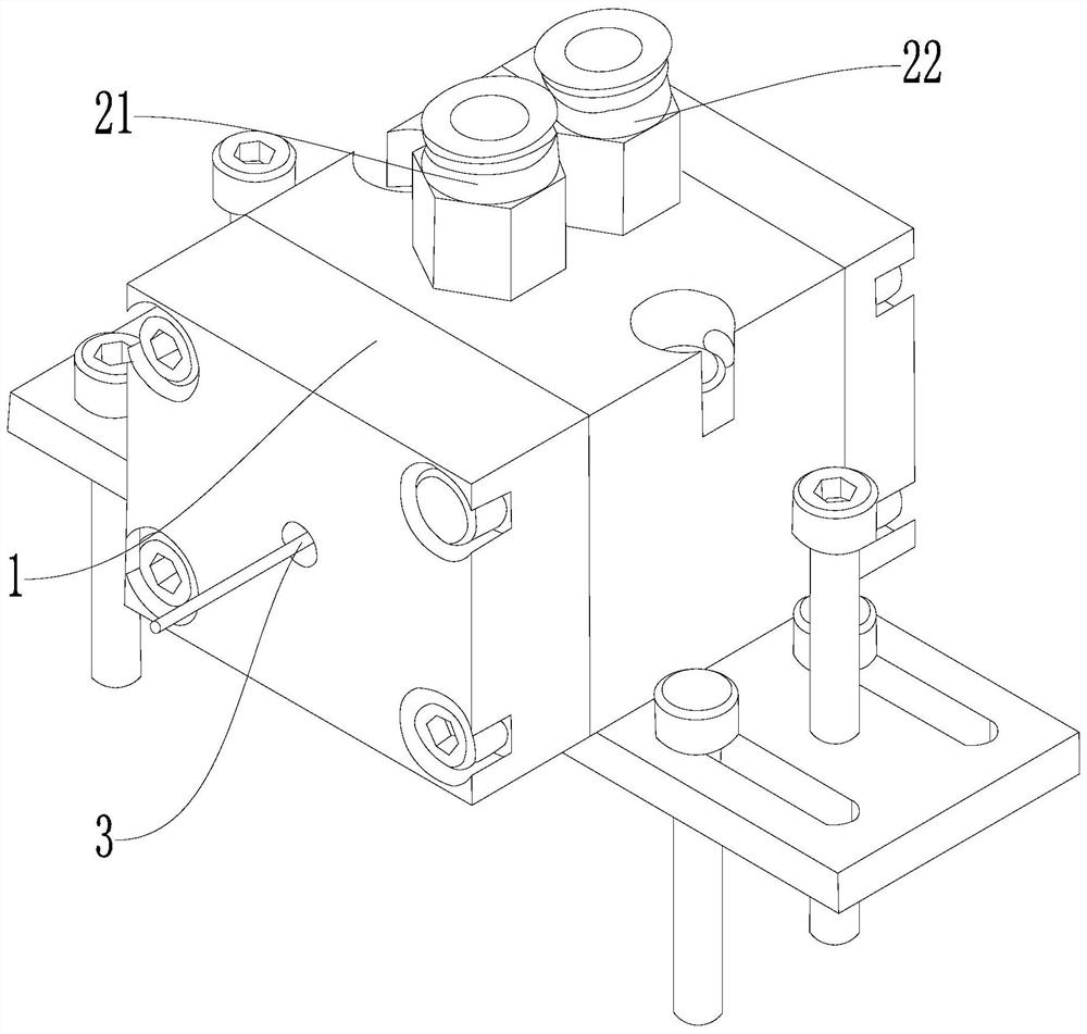
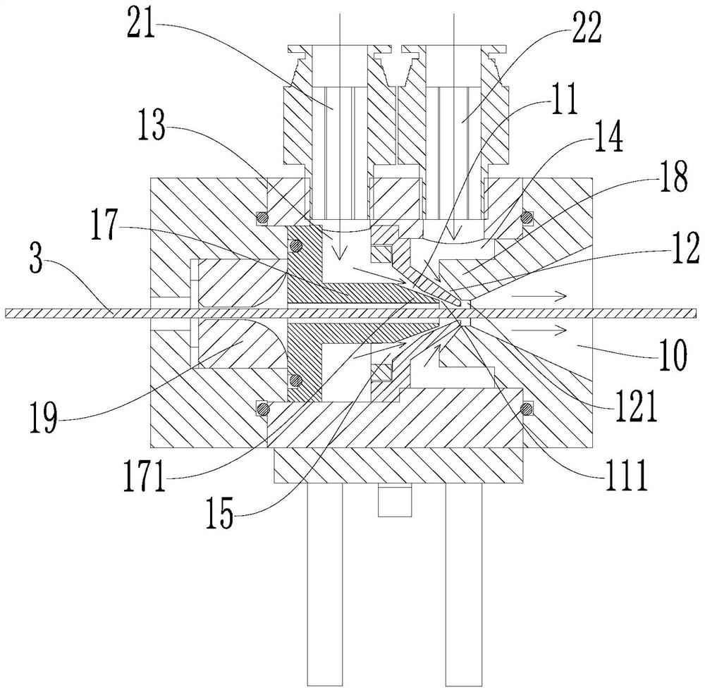
The invention discloses a welding wire air-blowing device which comprises a main body, an air inlet device and a driving device, the main body is provided with an air inlet channel communicated with the outside and an air-blowing channel for conveying welding wires, the air inlet channel is communicated with the air-blowing channel, and the air-blowing channel comprises a first conical channel and a second conical channel in the flowing direction of air. The welding wire sequentially passes through the second conical channel and the first conical channel, gas entering the first conical channel from the gas inlet channel is accelerated to enter the second conical channel, and gas in the second conical channel is accelerated to be exhausted to the outside; the gas inlet device is communicated to the gas inlet channel, and the flowing direction of gas entering the gas blowing channel from the gas inlet channel is opposite to the conveying direction of the welding wire; the driving device is used for driving the welding wire to move and driving the air inlet device; the gas is blown to the surface of the welding wire after being accelerated, the removal effect on the liquid on the surface of the welding wire is better, and the liquid on the surface of the welding wire is removed by accelerating the gas through the first conical channel and the second conical channel.

Description

technical field [0001] The invention belongs to the field of welding wire processing, and particularly relates to a welding wire air blowing device. Background technique [0002] Since the surface of the welding wire will produce small unevenness, the friction force will increase during use, which will affect the quality of the product; the copper plating technology of the welding wire is generally used in the existing technology, which can not only lubricate the welding wire, but also play a role in the welding wire. Rust-proof, conductive and reduces wear on wire feed contact tips. [0003] In the copper plating process of solid wire, in order to ensure the surface quality of the wire, each process needs to remove the liquid brought by the previous process, so the removal speed of the liquid on the surface of the wire also determines the copper plating speed of the wire. With the continuous improvement of the welding wire, the existing air blowing method cannot meet the r...

Claims


Application Information

Patent Timeline
Patent Type & Authority Applications(China)
IPC IPC(8): F26B13/00F26B21/00F26B25/00B08B5/02B08B13/00
CPCF26B13/00F26B21/001F26B25/00B08B5/023B08B13/00Y02P70/10
Inventor 薛海潮张林周福录孙猛石彬
Owner 德州市立尊焊丝有限公司
Why Eureka
Try Eureka