
Current-limiting protection circuit of power transistor

A power transistor and current limiting protection technology, applied in electronic switches, electrical components, regulating electrical variables, etc., can solve the problems of chip damage, current limiting protection is not timely, the circuit cannot start normally, etc. The effect of high circuit stability

Pending Publication Date: 2022-06-24
SG MICRO
View PDF0 Cites 5 Cited by
  • Summary
  • Abstract
  • Description
  • Claims
  • Application Information

AI Technical Summary

Problems solved by technology

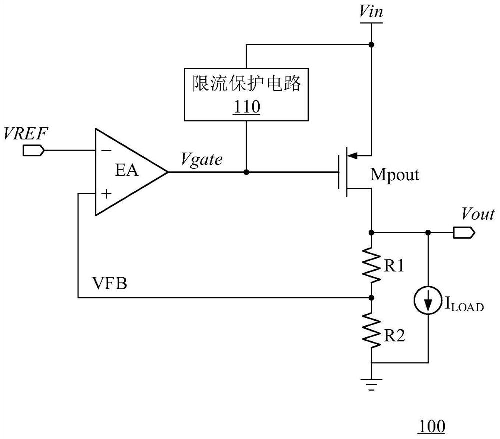
[0005] The current-limiting protection circuit of the existing power transistor has the following problems: the current-limiting threshold in the current-limiting protection circuit of the prior art is fixed, if the current-limiting threshold is set too small, if the subsequent stage load is slightly larger than the current-limiting protection circuit During the power-on process of the circuit, due to the low output voltage at this time, the current-limiting protection circuit will mistakenly believe that a load short circuit occurs at this time, and clamp the gate voltage of the power transistor to a certain value, resulting in the circuit not starting normally. ; If the current-limiting threshold is set too large, the current-limiting protection circuit cannot normally play the role of current-limiting, and the current-limiting protection may not be timely, resulting in chip damage

Method used


Image

  • Current-limiting protection circuit of power transistor
  • Current-limiting protection circuit of power transistor
  • Current-limiting protection circuit of power transistor

Examples


Embodiment Construction

[0024] Various embodiments of the present invention will be described in more detail below with reference to the accompanying drawings. In the various figures, the same elements are designated by the same or similar reference numerals. For the sake of clarity, various parts in the figures have not been drawn to scale.

[0025] It should be understood that in the following description, "circuitry" may include single or multiple combined hardware circuits, programmable circuits, state machine circuits, and / or elements capable of storing instructions executed by the programmable circuits. When an element or circuit is referred to as being "connected" to another element or an element / circuit is "connected" between two nodes, it may be directly coupled or connected to the other element or intervening elements may be present, and the connection between the elements may be be physical, logical, or a combination thereof. In contrast, when an element is referred to as being "directly...


PUM


Abstract

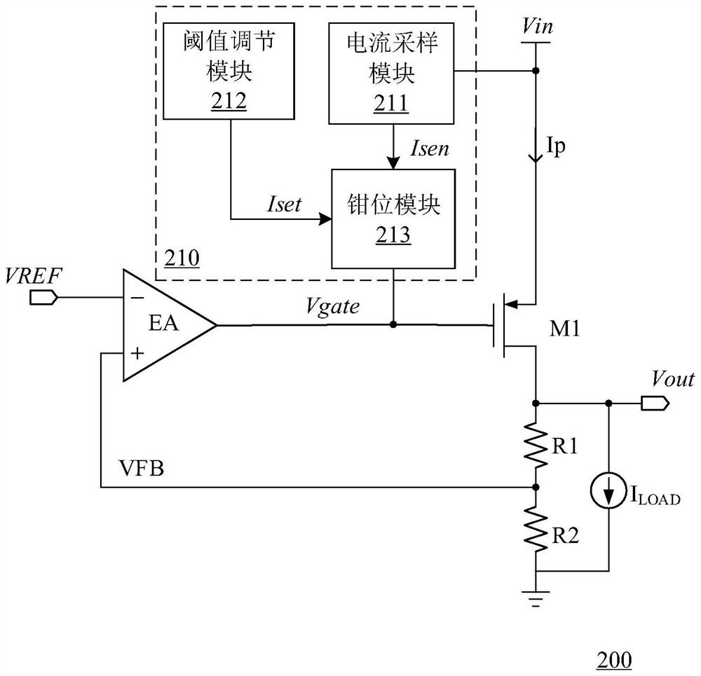
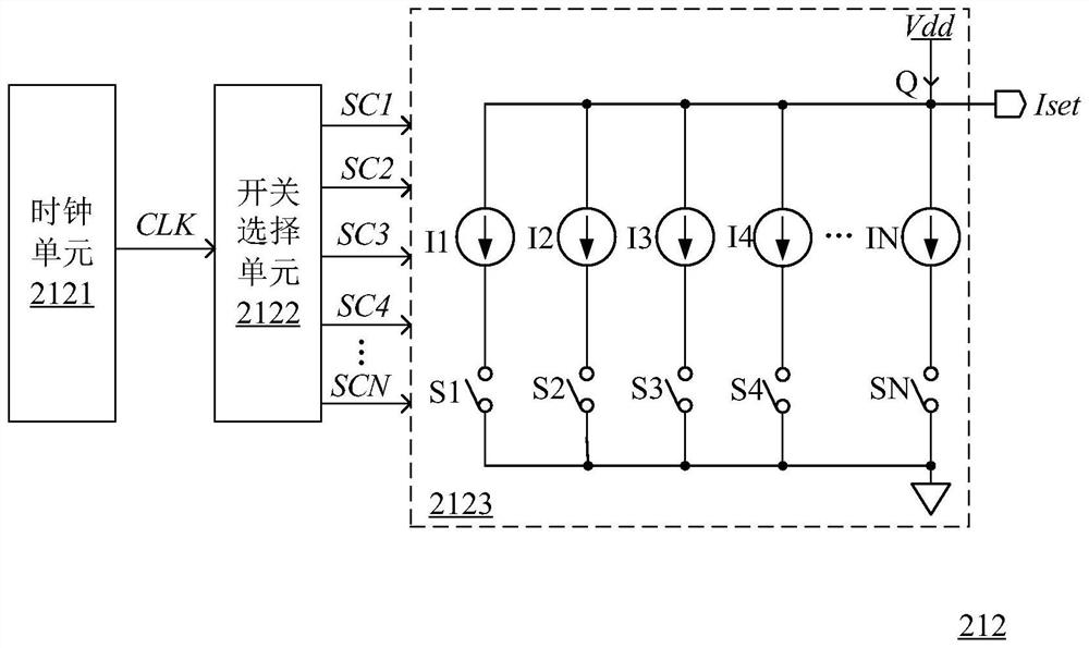
The invention discloses a current-limiting protection circuit of a power transistor. The current-limiting protection circuit comprises a current sampling module, a threshold adjusting module and a clamping module. The threshold value adjusting module is used for providing a reference current representing a current limiting threshold value, and the clamping module is used for feeding back and controlling the grid voltage of the power transistor under the condition that the sampling current is greater than the reference current so as to clamp the load current of the power transistor to the current limiting threshold value, the threshold value adjusting module is further used for controlling the reference current to increase progressively along with time when the power transistor is in an intermediate state between a turn-off state and a turn-on state, so that normal starting of the circuit is prevented from being affected by misoperation of the current-limiting protection circuit in the starting process of the circuit, and normal starting of the circuit can be guaranteed in the starting stage of the power transistor. Therefore, the load current is gradually changed from dozens of milliamperes to several amperes, the soft start of the power transistor is realized, and the power transistor and a post-stage load are protected.

Description

technical field [0001] The present invention relates to the technical field of switching power supplies, and more particularly, to a current limiting protection circuit of a power transistor. Background technique [0002] Power transistors are widely used in various power management systems and are an important part of power supply and system monitoring products. In the power management system, a MOSFET (Metal-Oxide-Semiconductor Field-Effect Transistor, metal-oxide semiconductor field effect transistor) is generally selected to provide a stable output voltage by adjusting the control voltage of the power transistor. [0003] At present, the trend of voltage-stabilizing circuit chips is to integrate power discrete devices into the chip as much as possible, which means that the power consumption inside the chip will become larger, especially when overload or even short circuit occurs, the power tube will pass through a large amount of time for a long time. The current may ca...

Claims


Application Information

Patent Timeline
Patent Type & Authority Applications(China)
IPC IPC(8): G05F1/56H03K17/08
CPCG05F1/56H03K17/08
Inventor 肖飞于翔
Owner SG MICRO
Learn More