Anti-poaching trigger device for wild animals and plants in protected area
A technology for wild animals and triggering devices, applied in circuit devices, transportation and packaging, battery circuit devices, etc., can solve the problems of large accidental touches, limited supervision conditions, and non-triggering devices, so as to improve service life, reduce maintenance frequency, The effect of reducing labor
- Summary
- Abstract
- Description
- Claims
- Application Information
AI Technical Summary
Problems solved by technology
Method used
Image
Examples
Embodiment 1
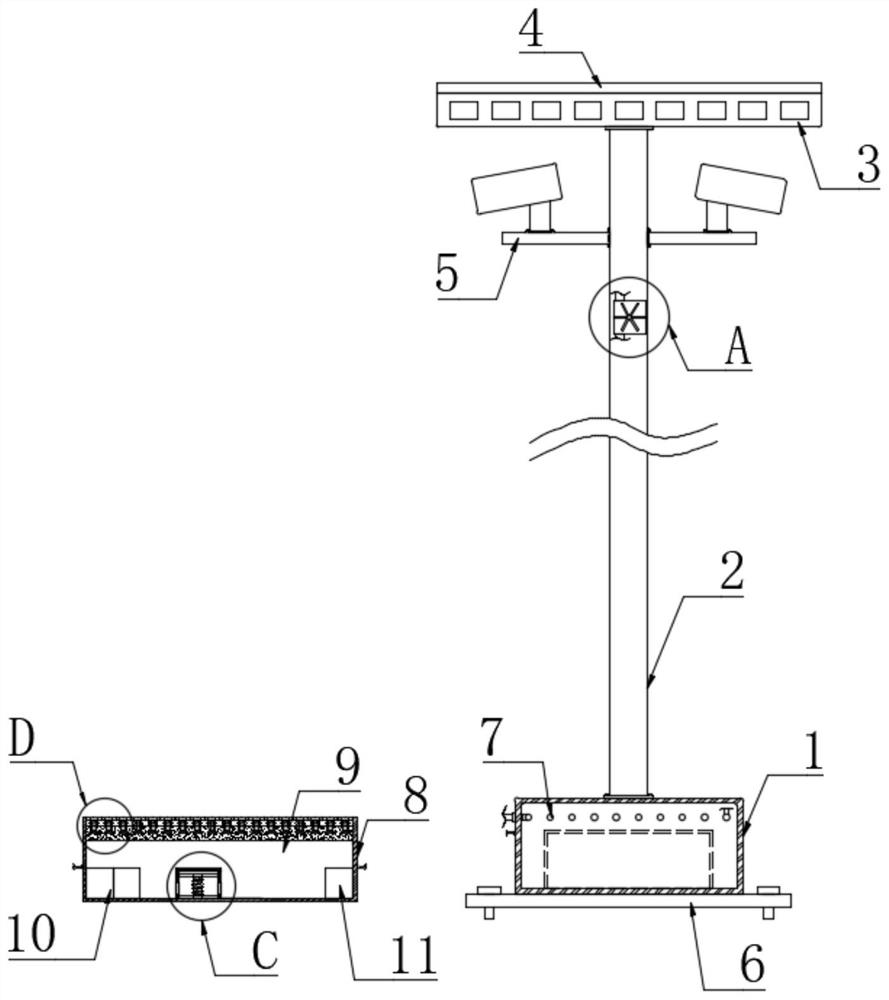
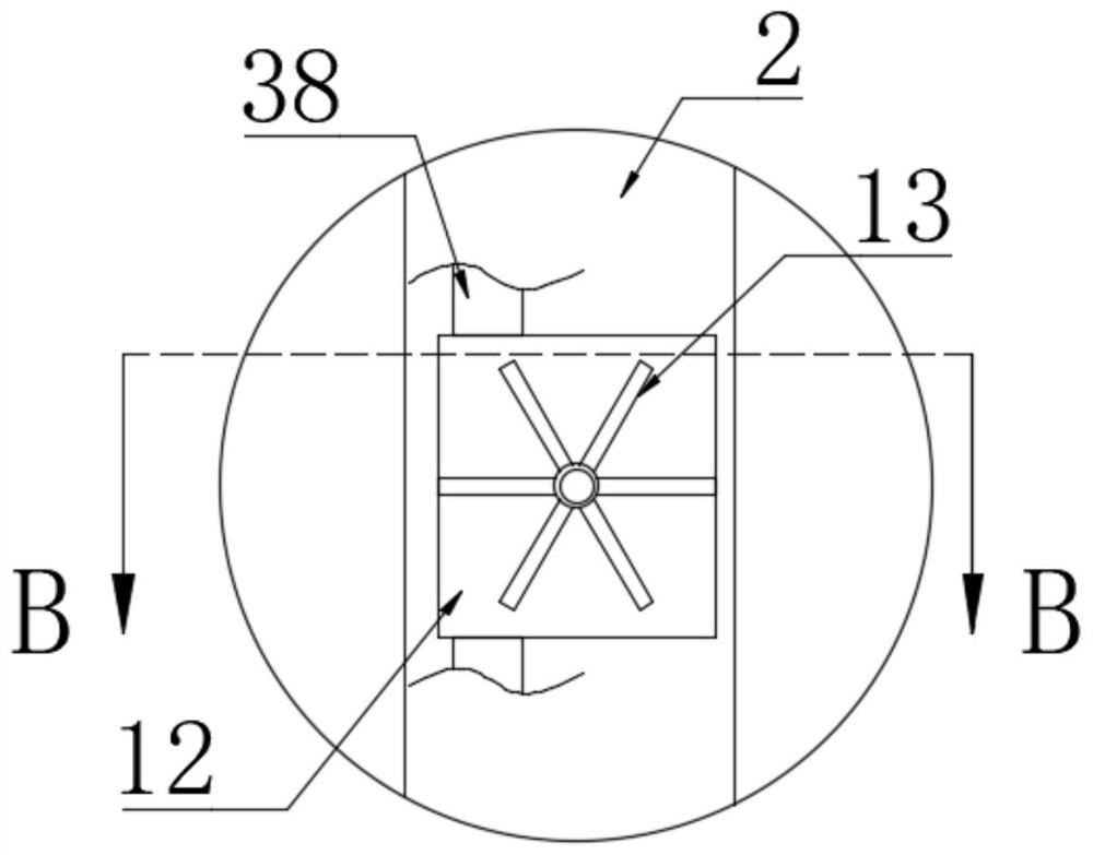
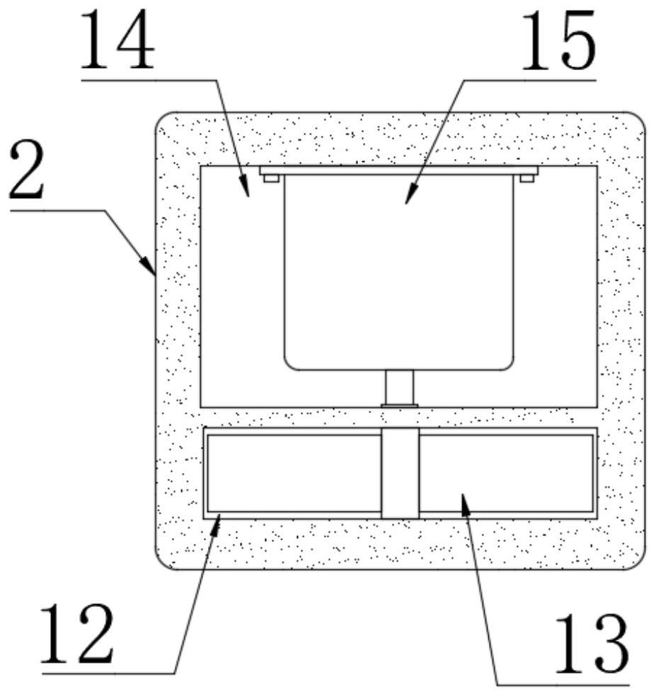
[0031] refer to Figure 1-5 , a protected wild animal and plant anti-theft hunting trigger device, including an installation box 1 and a plurality of trigger boxes 8, the trigger box 8 is made of stainless steel, the lower end of the installation box 1 is installed with a chassis 6, and the chassis 6 is installed with a plurality of Screws, the device is fixed in a proper position by screws, the upper end of the installation box 1 is fixedly connected to the support rod 2, and a plurality of camera assemblies 5 are installed on the side wall of the support rod 2, and the camera assembly 5 includes a connecting plate and a camera, through the camera head The road into the mountain can be monitored. When there are poachers, the staff can retrieve the camera information to confirm, and if it is determined to be a poacher, the alarm can be issued. There is a control cavity in the installation box 1, and there is a control cavity in the control cavity. The control chamber is provid...
Embodiment 2
[0040] refer to Image 6 The difference between this embodiment and Embodiment 1 is that the left and right inner walls of the trigger slot 9 are fixedly connected with a support plate 29, the upper end of the support plate 29 is installed with a pressure sensor 30, and the upper end of the pressure sensor 30 is in contact with the lower end of the mounting plate 16. , the pressure sensor 30 can detect the magnitude of the pressure, and convert the magnitude of the pressure into the magnitude of the current passed into the second electromagnet 32 through equipment such as AD converters and single-chip microcomputers. The right side of the first auxiliary box 23 is installed with a second auxiliary The box 31, the second auxiliary box 31 is provided with a second trigger cavity, the inner bottom of the second trigger cavity is installed with a second electromagnet 32, the second trigger cavity is slidably connected with a second magnet block 33, the second magnet block 33 The...
Embodiment 3
[0043] refer to Figure 7 The difference between this embodiment and Embodiment 1 is that a second serpentine heat dissipation pipe 36 is installed in the trigger slot 9, and connecting pipes 37 are provided on the left and right sides of the trigger box 8, and the left and right connecting pipes 37 are located on the right The two ends are respectively connected with the air inlet of the second serpentine radiating pipe 36 and the air outlet of the first serpentine radiating pipe 7, and the connecting pipe 37 on the left is communicated with the outside world, and the air introduced by the air collecting box 3 will pass through in turn. The auxiliary pipe 38, the first serpentine radiating pipe 7, the connecting pipe 37 and the plurality of second serpentine radiating pipes 36 ensure the heat dissipation of the electronic components in each trigger box 8, and also ensure that the device has a lot of airtightness and is difficult to dust. Enter, improve the time life of the de...
PUM
 Abstract
Description
Claims
Application Information
 - R&D
- Intellectual Property
- Life Sciences
- Materials
- Tech Scout
- Unparalleled Data Quality
- Higher Quality Content
- 60% Fewer Hallucinations
Browse by: Latest US Patents, China's latest patents, Technical Efficacy Thesaurus, Application Domain, Technology Topic, Popular Technical Reports.
© 2025 PatSnap. All rights reserved.Legal|Privacy policy|Modern Slavery Act Transparency Statement|Sitemap|About US| Contact US: help@patsnap.com


