Cutting machine with detection structure for electronic material processing

A technology for electronic materials and detection structures, which is used in metal processing equipment, glass cutting devices, manufacturing tools, etc., and can solve problems such as inability to place workpieces in suitable positions and lack of feeding devices.

Pending Publication Date: 2022-06-28
NANTONG DINGSHANG ELECTRONICS MATERIAL CO LTD
View PDF11 Cites 1 Cited by
  • Summary
  • Abstract
  • Description
  • Claims
  • Application Information

AI Technical Summary

Problems solved by technology

This cutting machine for glass processing that is easy to adjust the distance can cut different curves by adjusting the distance vertically and horizontally.” The device lacks a feeding device and cannot accurately discharge the workpiece in a suitable position

Method used


Image

  • Cutting machine with detection structure for electronic material processing
  • Cutting machine with detection structure for electronic material processing
  • Cutting machine with detection structure for electronic material processing

Examples


Embodiment 1

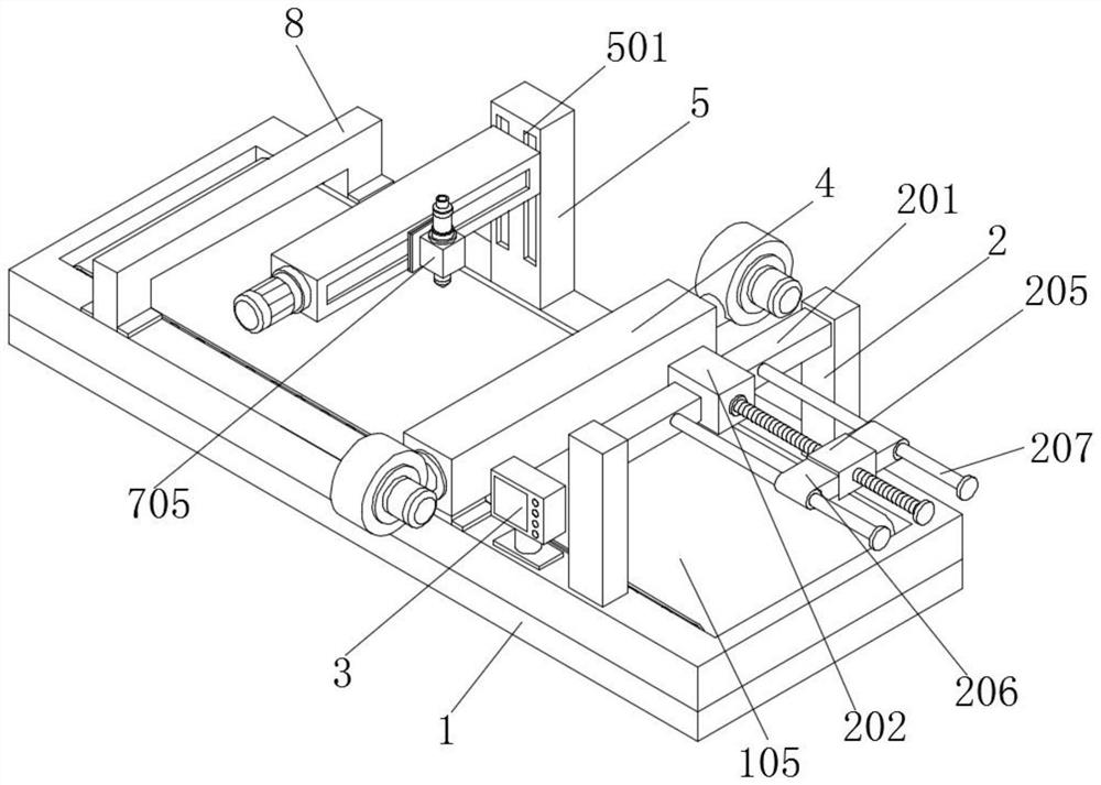
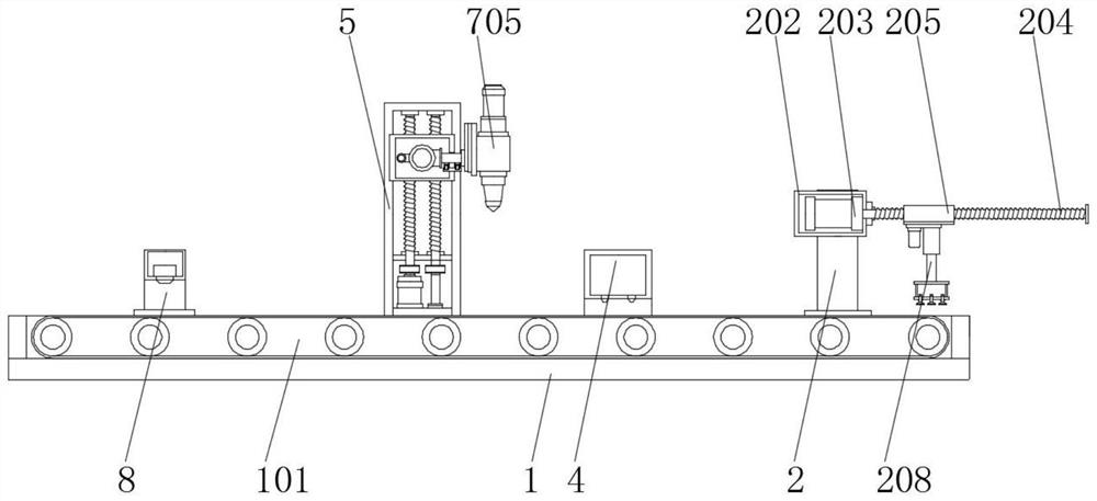
[0044] The first embodiment includes a bottom plate 1, a support box 101 is installed on the top of the bottom plate 1, and the bottom plate 1 supports the top support box 101 to ensure the stability of the support box 101. The transmission rod 103, one end of the transmission rod 103 is installed with a control motor 102, the control motor 102 is installed on the inner side of the support box 101, the outer side of the transmission rod 103 is installed with a transmission roller 104, the outer side of the transmission roller 104 is installed with a conveyor belt 105, the transmission rod The other end of 103 is installed with a transmission wheel 106, the transmission wheel 106 is located on the inner side of another group of support boxes 101, and the outer side of the transmission wheel 106 is covered with a transmission belt 107, which controls the operation of the motor 102 to drive the transmission rod 103 of the output end to rotate counterclockwise, and the transmission ...

Embodiment 2

[0046] The second embodiment includes a support box 101, the top of the support box 101 is mounted with a controller 3 through bolts, and the operation of the device is controlled by the controller 3, which is convenient for workers to operate. The controller 3 is located behind the fixed column 2, and the A mounting seat 401 is mounted on the top of the support box 101 through bolts, and the mounting seat 401 is located behind the controller 3 , a ventilation box 4 is mounted on the top of the mounting seat 401 , and a blower 402 is installed through both sides of the ventilation box 4 . , the bottom of the ventilation box 4 is provided with a blowing hole 403, and the ventilation box 4 is fixed on the top of the support box 101 through the mounting seat 401 to ensure the stability of the device and facilitate the installation of the ventilation box 4. The blower 402 operates to blow the air outside Enter the inside of the ventilation box 4, so that the air pressure inside the...

Embodiment 3

[0048]The third embodiment includes a support box 101, the top of the support box 101 is mounted with a support column 5 through bolts, and the support column 5 is located on one side of the mounting seat 401, and a guide groove is opened on one side of the outer wall of the support column 5 501, a servo motor 502 is installed on the bottom arm of the support column 5, a second screw 503 is installed on the output end of the servo motor 502, a driving wheel 504 is installed on the outside of the second screw 503, and a first screw is installed on the inside of the support column 5. Three screws 507, and the third screw 507 is located on one side of the second screw 503, a driven wheel 506 is installed on the outer side of the third screw 507, a transmission belt 505 is installed on the outer side of the driven wheel 506, and the transmission belt 505 is connected with the driving wheel 504 through the transmission belt 505 , the operation of the servo motor 502 drives the secon...


PUM


Abstract

The electronic material processing cutting machine with the detection structure comprises a bottom plate, a supporting box is mounted at the top of the bottom plate, fixing columns are mounted at the top of the supporting box through bolts, supporting rods are mounted on the opposite faces of the two fixing columns, a mounting shell is mounted at one end of each supporting rod, and a detection structure is mounted at the other end of each supporting rod. A driving motor is mounted in the mounting shell, and the output end of the driving motor is connected with a first screw rod; a controller is mounted at the top of the supporting box through bolts and located behind the fixing columns. The ultrasonic flaw detection device is installed, an ultrasonic generator in the ultrasonic flaw detection device emits ultrasonic waves to a workpiece passing through the lower portion, the ultrasonic waves penetrate through the interior of the workpiece and then are reflected, and an ultrasonic receiver in the ultrasonic flaw detection device receives the returned ultrasonic waves; whether scars exist in the cut workpiece or not is known, and the workpiece cutting quality is confirmed.

Description

technical field [0001] The invention relates to the technical field of electronic material processing, in particular to a cutting machine for electronic material processing with a detection structure. Background technique [0002] Electronic materials refer to the materials that need to be used in electronic technology. There are many electronic materials, including semiconductor materials, piezoelectric and ferroelectric materials, conductive metals and their alloy materials. In the process of processing, it is necessary to The material is slitted by a cutting machine. [0003] The defects of the cutting machine in the prior art are: [0004] 1. The reference document CN210648813U discloses a cutting mechanism for copper parts processing, "including a fixing mechanism, a driving motor, a cutting platform and a start switch, wherein: the fixing mechanism includes a vertical support column, a power platform and an installation slot, and the fixing mechanism It is formed by ...

Claims


Application Information

Patent Timeline
Patent Type & Authority Applications(China)
IPC IPC(8): B23K26/16B23K26/38B23K26/70C03B33/08
CPCB23K26/38C03B33/082B23K26/702B23K26/16
Inventor 葛建平
Owner NANTONG DINGSHANG ELECTRONICS MATERIAL CO LTD
Why Eureka
Try Eureka