Check patentability & draft patents in minutes with Patsnap Eureka AI!

Mechanical transmission decoupling method for multi-axis robot

A multi-axis robot and mechanical transmission technology, applied in the direction of manipulators, program-controlled manipulators, manufacturing tools, etc., can solve the problems of increasing robot calculation and control accuracy errors, increasing the complexity of control and control algorithms, and different speed adjustment ranges. The difficulty of control, low requirements, and the effect of reducing accuracy errors

Pending Publication Date: 2022-06-28
CHANGSHA CTR ROBOTICS
View PDF6 Cites 0 Cited by
  • Summary
  • Abstract
  • Description
  • Claims
  • Application Information

AI Technical Summary

Problems solved by technology

[0003] In order to improve the heat resistance of grabbing high-temperature workpieces, greatly reduce the mass of the front end of the robot, lower the center of gravity of the robot, and improve the motion stability of the robot, the robot layout generally adopts a rear-mounted motor scheme, that is, the robot's 5-axis and 6-axis motors are rear-mounted, Putting it in the position of the big arm ensures the small shape of the end of the robot, but it also brings some problems to the mechanical transmission, that is, the transmission coupling. The transmission coupling will bring the following problems: 1. Control decoupling is required in the motor drive control, because the control solution Coupling and robot series pose calculations affect each other, greatly increasing the difficulty of control and the complexity of control algorithms
2. Due to the existence of transmission coupling and the influence of robot series pose calculation, the accuracy error of robot calculation and control is increased
3. Due to the existence of transmission coupling, each axis has a different range of motor speed regulation, resulting in more and stricter requirements for motor speed regulation characteristics

Method used


Image

  • Mechanical transmission decoupling method for multi-axis robot
  • Mechanical transmission decoupling method for multi-axis robot
  • Mechanical transmission decoupling method for multi-axis robot

Examples


Embodiment Construction

[0072] The present invention will be described in detail below with reference to the accompanying drawings. The description in this part is only exemplary and explanatory, and should not have any limiting effect on the protection scope of the present invention. In addition, according to the description in this document, those skilled in the art can make corresponding combinations of features in the embodiments in this document and in different embodiments.

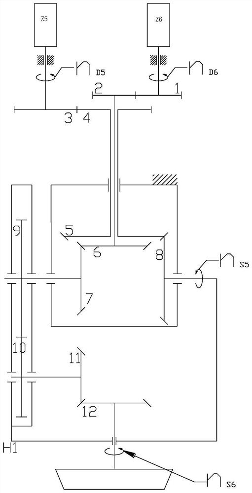
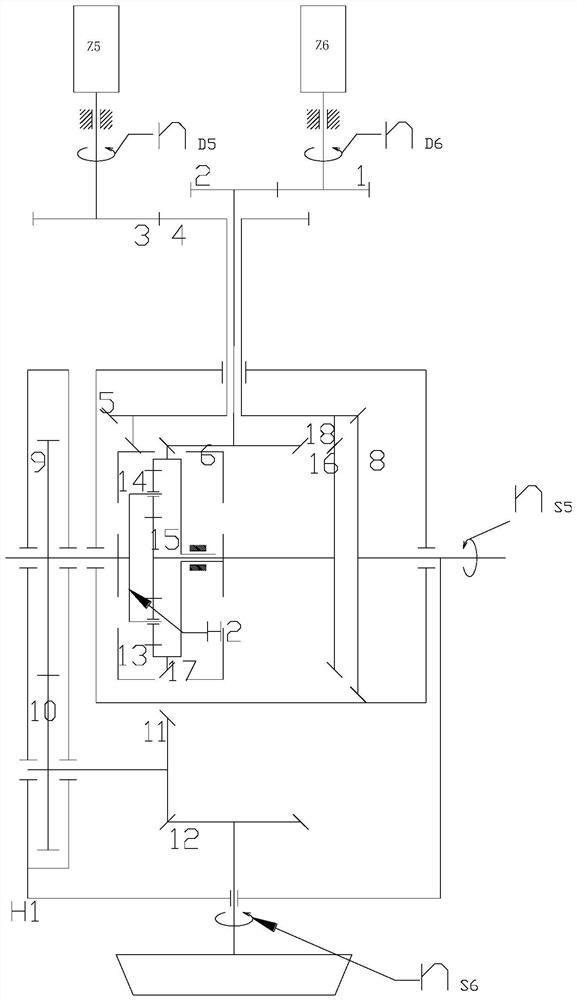
[0073] Examples of the present invention are as follows, refer to figure 1 , a method for decoupling the mechanical transmission of a multi-axis robot, comprising the following steps:

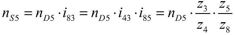
[0074] (1) The original mechanical transmission condition is analyzed and refined, and the original transmission function relationship is obtained, in which the rotational speed of the working unit of one axis is the dependent variable, and the factor affecting the rotational speed of the working unit of the axis is the independent variable...


PUM


Abstract

The invention relates to a mechanical transmission decoupling method for a multi-axis robot, which comprises the following steps of: (1) analyzing and extracting original mechanical transmission working conditions to obtain an original transmission function relational expression; (2) designing a differential gear box, and carrying out mathematical analysis on the differential gear box; (3) determining a decoupling transmission relation analytic expression; (4) determining a transmission structure according to the transmission relation of the decoupling transmission relation analytic expression; and (5) checking the transmission relation structure to meet the geometrical relation of the structure and ensure the practicability. According to the implementation of the technical scheme, transmission of all shafts of the robot is independent and is not mutually coupled, control decoupling is not needed in robot motor driving control, and the control difficulty and the complexity of a control algorithm are greatly reduced; precision errors of robot calculation and control are reduced; the requirement for the speed regulation characteristic of the motor is low, and the difficulty of motor design and model selection is reduced.

Description

technical field [0001] The invention belongs to the technical field of multi-axis robot application, and in particular relates to a method for decoupling mechanical transmission of a multi-axis robot. Background technique [0002] A robot is an intelligent machine that can work semi-autonomously or fully autonomously. It can assist or even replace human beings to complete dangerous, heavy and complex work, improve work efficiency and quality, serve human life, and expand or extend human activities and capabilities. The robot drives the work unit to generate movement through the drive system, so as to complete the required action. The robot transmission system is a device that transmits the motion and power output by the driver to the work unit. There are many ways of transmission system, and mechanical transmission is a common way. [0003] In order to improve the heat resistance of grasping high-temperature workpieces, greatly reduce the quality of the front end of the ro...

Claims


Application Information

Patent Timeline
Patent Type & Authority Applications(China)
IPC IPC(8): B25J9/16
CPCB25J9/1679
Inventor 王力吴葛铭杨倩倩罗堃谭思雨
Owner CHANGSHA CTR ROBOTICS
Features
  • R&D
  • Intellectual Property
  • Life Sciences
  • Materials
  • Tech Scout
  • Unparalleled Data Quality
  • Higher Quality Content
  • 60% Fewer Hallucinations
Learn More