Deep hole blasting vibration reduction method

A technology of deep hole blasting and blasting, which is applied in blasting and other directions, can solve problems such as affecting the effective utilization rate of blast energy, and achieve the effect of improving blasting effect, novel design, and beneficial to uniform crushing.

Pending Publication Date: 2022-06-28
ANHUI MASTEEL MINING RESOURCES GRP NANSHAN MINING CO LTD +1
View PDF5 Cites 0 Cited by
  • Summary
  • Abstract
  • Description
  • Claims
  • Application Information

AI Technical Summary

Problems solved by technology

Theoretical and practical studies have shown that the change of the charge structure can cause the energy distribution of the explosive in the direction of the blast hole, thereby affecting the effective utilization of the explosion energy

Method used


Image

  • Deep hole blasting vibration reduction method
  • Deep hole blasting vibration reduction method
  • Deep hole blasting vibration reduction method

Examples


Embodiment 1

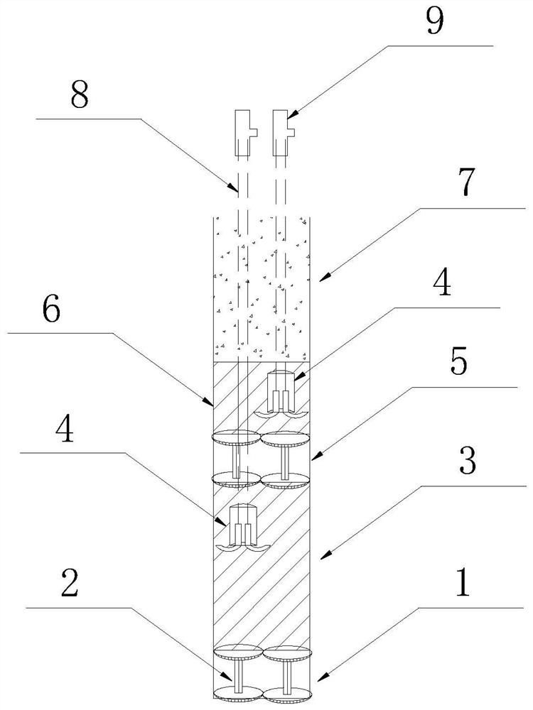
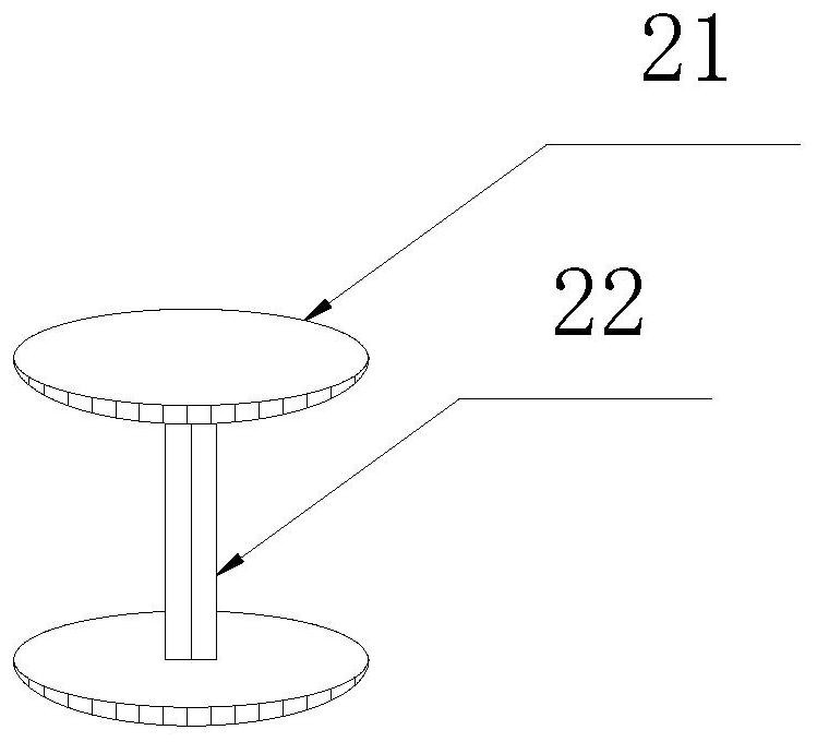
[0045] like figure 1 and figure 2 As shown in the figure, a deep-hole blasting vibration-damping charge structure of the present invention includes a blasting hole 11, and the blasting hole 11 is respectively set from bottom to top as a hole bottom supporting interval 1, a lower explosive filling section 3, and a supporting interval between the holes. Section 5, inter-hole explosive filling section 6 and rock powder filling section 7; the hole-bottom support interval section 1 and the inter-hole support interval section 5 are respectively provided with a number of support frames 2. A spaced section with air or water is formed between the bottom and the hole; the rock powder filling section 7 is formed by filling with rock powder; the lower explosive filling section 3 and the explosive filling section 6 between the holes are respectively formed by filling explosives, and the two explosives are filled with The tops of the sections are respectively provided with detonating char...

Embodiment 2

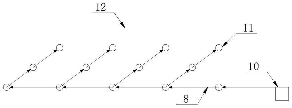
[0050] like Figure 1 to Figure 3 As shown, a deep hole blasting vibration damping structure of the present invention is composed of the deep hole blasting vibration damping charge structures described in several embodiments 1. Connectors 9 are connected to each connector 9, and each connector 9 is connected to a shot area network 12 through a detonating cord 8, and a detonator 10 is connected to the shot area network 12.

[0051] Further, each blast hole 11 can be connected by detonating cord 8 to realize hole-by-hole differential blasting, specifically: several blast holes 11 are arranged in a row, the distance between adjacent blast holes 11 is 8-9m, and each row of blast holes is 8-9m apart. The holes 11 are evenly arranged at parallel intervals, and the row spacing of two adjacent rows of gun holes 11 is 5.5-6m. The connectors 9 connected to the detonating cords 8 on the detonating charge packs 4 in the outermost row of gun holes 11 are connected by the detonating cords 8...

Embodiment 3

[0053] like Figure 1-Figure 3 As shown, a deep hole blasting vibration damping method of the present invention, the steps are as follows:

[0054] S1. On the step where blasting is required in the open-pit iron ore, determine the position of each blast hole 11 according to the blasting requirements, and use a roller cone drill to carry out the perforation operation of each blast hole 11. According to the designed blasting parameters, until the perforation operation of each blast hole 11 is completed, The depth of the blast hole 11 is usually set to 14.5-15m, and the diameter is 250-310mm. Each blast hole 11 is set from bottom to top as the hole bottom support interval 1, the lower explosive filling section 3, the hole support interval 5, Inter-hole explosive filling section 6 and rock powder filling section 7;

[0055] S2. Slowly put several support frames 2 into the positions of the pre-designed interval sections at the bottom of the gun hole 11 through the string to form t...


PUM


Abstract

The invention discloses a deep hole blasting vibration reduction method, which belongs to the technical field of deep hole blasting, and comprises the following steps of: respectively arranging a hole bottom support interval section, a lower explosive filling section, an inter-hole support interval section, an inter-hole explosive filling section and a rock powder filling section in each blast hole from bottom to top according to a distance, and charging the two explosive filling sections in sections; meanwhile, a water interval or an air interval is formed in the two interval sections through the supporting frame, then segmented blasting is carried out, the explosive use amount and the maximum section explosive amount are reduced, then blasting vibration is reduced, the blasting effect is improved, no bottom root exists after blasting, the blasting cost is reduced, the mine economic benefits are improved, and practicability is high.

Description

technical field [0001] The invention belongs to the technical field of deep-hole blasting in open-pit iron ore, and relates to a deep-hole blasting vibration damping method. Background technique [0002] At present, deep hole blasting is mostly used in large open-pit mines, and the quality of blasting effect is crucial to the subsequent process flow and mining cost. At present, most open-pit mines have problems such as the production of large blocks and the unreasonable distribution of blast piles, which leads to high production costs of mines. At the same time, excessive blasting vibration will also affect auxiliary equipment, buildings and interfere with the lives of surrounding residents. [0003] It is generally believed that the fragmentation of rocks is the result of the combined action of shock waves and the expansion pressure of explosive gases. The energy released by the explosive when it explodes in the rock mass is transmitted to the rock through the explosion st...

Claims


Application Information

Patent Timeline
Patent Type & Authority Applications(China)
IPC IPC(8): F42D1/00F42D1/10F42D3/04F42D5/045F42D1/04
CPCF42D1/00F42D1/10F42D3/04F42D5/045F42D1/04
Inventor 曹蕾卜维平陈红权贺笑于士峰朱龙龙李尚孔攀张祝亭谢建德
Owner ANHUI MASTEEL MINING RESOURCES GRP NANSHAN MINING CO LTD
Why Eureka
Try Eureka