High-integration photoacoustic gas sensor based on optical path optimization
A photoacoustic gas, optical path optimization technology, applied in instruments, scientific instruments, material analysis by optical means, etc., can solve the problems of difficult miniaturization of photoacoustic sensors, large volume of closed photoacoustic cells, and low degree of integration. Achieve the effect of saving cost and processing complexity, saving processing steps, and avoiding complex packaging
- Summary
- Abstract
- Description
- Claims
- Application Information
AI Technical Summary
Problems solved by technology
Method used
Image


Examples
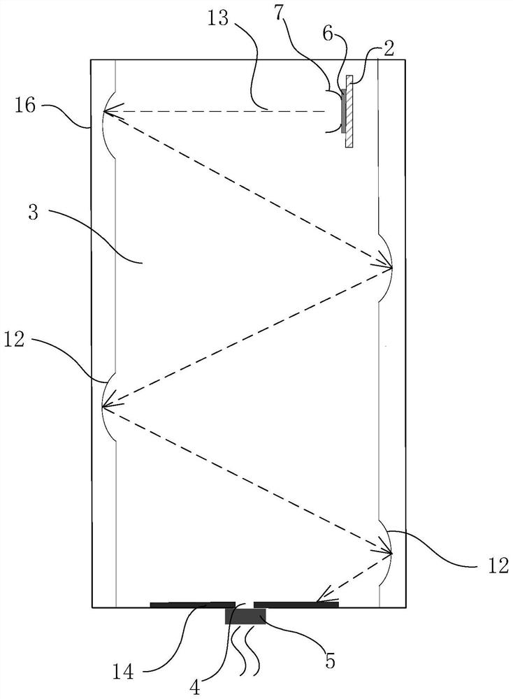
Embodiment 1
[0030] The present invention provides a highly integrated photoacoustic gas sensor based on optical path optimization, such as figure 1 As shown, it includes a substrate 1 , a housing 16 forming a sealed air chamber 3 with the substrate 1 , and a radiation source disposed in the air chamber 3 . In this embodiment, the casing 16 has a rectangular parallelepiped structure, and may also be a cube, a hemisphere, or the like. The substrate 1 plays the role of carrying internal components and providing circuit connections between the internal components. The air hole 4 is opened on the side shell 16 of the air chamber 3, which is used to communicate with the external gas environment, so that the air chamber 3 is filled with the gas to be measured; They are connected in an airtight manner such as bonding, so that an acoustically sealed structure is formed in the air chamber 3 . The waterproof and breathable membrane 5 can be selected from materials such as polymers.
[0031] A mic...
Embodiment 2
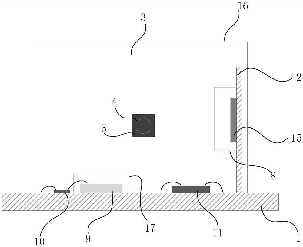
[0040] Compared with Embodiment 1, the difference of this embodiment is that the radiation source selects a laser chip 15, such as a vertical cavity surface emitting laser (vcsel) that can be integrated, such as image 3 and Figure 4 As shown, since the laser chip 15 itself can obtain the collimated light 13, the design of the condenser lens 7 is not required.
PUM
 Abstract
Description
Claims
Application Information
 - R&D
- Intellectual Property
- Life Sciences
- Materials
- Tech Scout
- Unparalleled Data Quality
- Higher Quality Content
- 60% Fewer Hallucinations
Browse by: Latest US Patents, China's latest patents, Technical Efficacy Thesaurus, Application Domain, Technology Topic, Popular Technical Reports.
© 2025 PatSnap. All rights reserved.Legal|Privacy policy|Modern Slavery Act Transparency Statement|Sitemap|About US| Contact US: help@patsnap.com