
High-potential current acquisition system suitable for 10cm-2m gap discharge process

A discharge process and acquisition system technology, applied in the direction of measuring current/voltage, measuring electrical variables, testing dielectric strength, etc., can solve the problems of being unable to apply to cross-scale gap discharge at the same time, and only applicable

Pending Publication Date: 2022-06-28
ELECTRIC POWER RESEARCH INSTITUTE, CHINA SOUTHERN POWER GRID CO LTD +1
View PDF2 Cites 0 Cited by
  • Summary
  • Abstract
  • Description
  • Claims
  • Application Information

AI Technical Summary

Problems solved by technology

[0005] Aiming at the defects and improvement requirements that the existing current acquisition is only suitable for 1m-2m long gap discharge, or only suitable for short gap discharge, and cannot be applied to cross-scale gap discharge at the same time, the present invention provides a method suitable for 10cm-2m gap discharge The high-potential current acquisition system during the discharge process aims to realize cross-scale and high-precision current acquisition and measurement in long and short gaps

Method used


Image

  • High-potential current acquisition system suitable for 10cm-2m gap discharge process
  • High-potential current acquisition system suitable for 10cm-2m gap discharge process
  • High-potential current acquisition system suitable for 10cm-2m gap discharge process

Examples


Embodiment Construction

[0042] In order to make the objectives, technical solutions and advantages of the present invention clearer, the present invention will be further described in detail below with reference to the accompanying drawings and embodiments. It should be understood that the specific embodiments described herein are only used to explain the present invention, but not to limit the present invention. In addition, the technical features involved in the various embodiments of the present invention described below can be combined with each other as long as they do not conflict with each other.

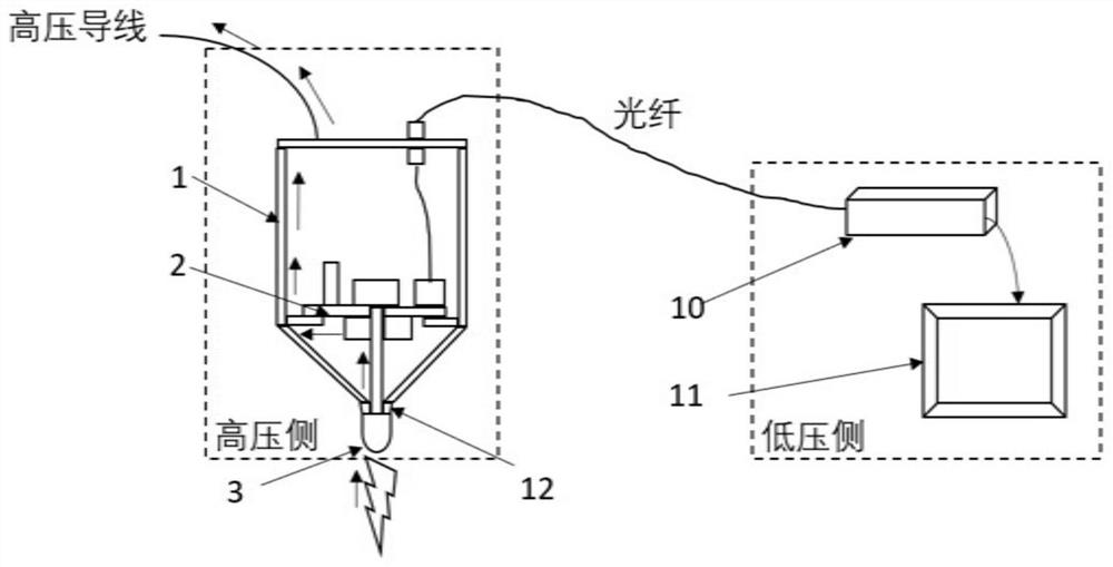
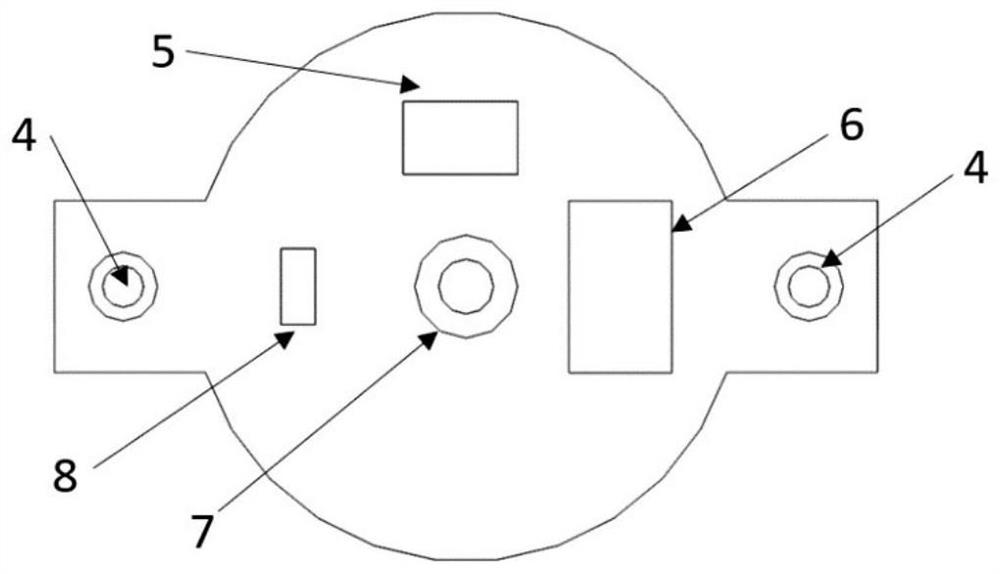
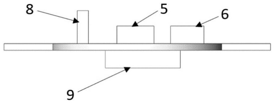
[0043] like figure 1 As shown, the present invention provides a high-potential current acquisition system suitable for a 10cm-2m gap discharge process, including a high-voltage side transceiver module and a low-voltage side transceiver module. The high-voltage end transceiver module collects the analog signal of the discharge current of the high-voltage end and outputs it as an optical signal, and ...


PUM

PropertyMeasurementUnit
wavelengthaaaaaaaaaa
electrical resistanceaaaaaaaaaa

Abstract

The invention discloses a high-potential current acquisition system suitable for a 10cm-2m gap discharge process, and belongs to the field of current measurement. The input end of a current injection path is connected with a high-voltage electrode, and the output end is connected with a sampling resistor; the resistance value R of the sampling resistor satisfies 10 omega < = R < = 400 omega, and the other end of the sampling resistor is in equipotential connection with the shielding case and is used for receiving a discharge current signal of the high-voltage electrode; the signal attenuator is adjustable, the attenuation range is 3-30 dB, and the signal attenuator is connected with the sampling resistor in parallel and used for attenuating the obtained voltage signal to the adjusted attenuation multiplying power; the bandwidth of the voltage follower is not less than 150MHz, the input end of the voltage follower is connected with the output end of the signal attenuator, the output end of the voltage follower is connected with the input end of the high-speed light emitter, and the voltage follower is used for providing a voltage input signal required by the high-speed light emitter; the bandwidth of the high-speed light emitter is higher than that of the voltage follower, and the output end of the high-speed light emitter is connected with the transmission optical fiber and used for directly converting the analog electric signals after voltage following into optical signals. According to the invention, cross-scale high-precision current acquisition and measurement are realized.

Description

technical field [0001] The invention belongs to the field of current measurement, and more particularly, relates to a high-potential current acquisition system suitable for a 10cm-2m gap discharge process. Background technique [0002] Rod-to-plate gap discharge is a strong ionization phenomenon in which a current flows if a voltage is applied to the upper two electrodes. In order to deeply study the physical mechanism of gap discharge, it is necessary to measure the current parameters generated during the discharge process, especially the discharge current generated by the high voltage terminal. The current bandwidth of this type is usually as high as tens of MHz, and the wavefront time is as low as tens of nanoseconds. Therefore, the bandwidth and sensitivity performance of the current acquisition system are required to meet the measurement requirements. In addition, for the measurement of the high-voltage side current, it is also necessary to solve the problem of electri...

Claims


Application Information

Patent Timeline
Patent Type & Authority Applications(China)
IPC IPC(8): G01R31/12G01R19/00
CPCG01R31/1218G01R19/00
Inventor 刘磊贾磊李敏郭黎黎潘锐健唐力李恩文李斌厉天威陈立学何俊佳
Owner ELECTRIC POWER RESEARCH INSTITUTE, CHINA SOUTHERN POWER GRID CO LTD
Learn More