
Movable sludge filter pressing device and technological process thereof

A sludge filter press and sludge technology, applied in sludge treatment, water/sludge/sewage treatment, mixer with rotating stirring device, etc., can solve the problem that it is not suitable to establish a sludge treatment system and cannot build sludge Treatment system, poor sludge treatment effect, etc., to save input costs and follow-up maintenance costs, avoid less sewage, and facilitate treatment

Pending Publication Date: 2022-07-01
华夏中然生态科技集团有限公司
View PDF8 Cites 0 Cited by
  • Summary
  • Abstract
  • Description
  • Claims
  • Application Information

AI Technical Summary

Problems solved by technology

[0005] The invention proposes a mobile sludge filter press device and its process flow, which solves the problem that the site of the sewage plant in the prior art is insufficient, and the sludge treatment system cannot be built, so that the sludge treatment effect is poor, and the area with a small amount of sludge sewage is not easy to use. Suitability for establishing a sludge treatment system

Method used


Image

  • Movable sludge filter pressing device and technological process thereof
  • Movable sludge filter pressing device and technological process thereof
  • Movable sludge filter pressing device and technological process thereof

Examples


Embodiment 1

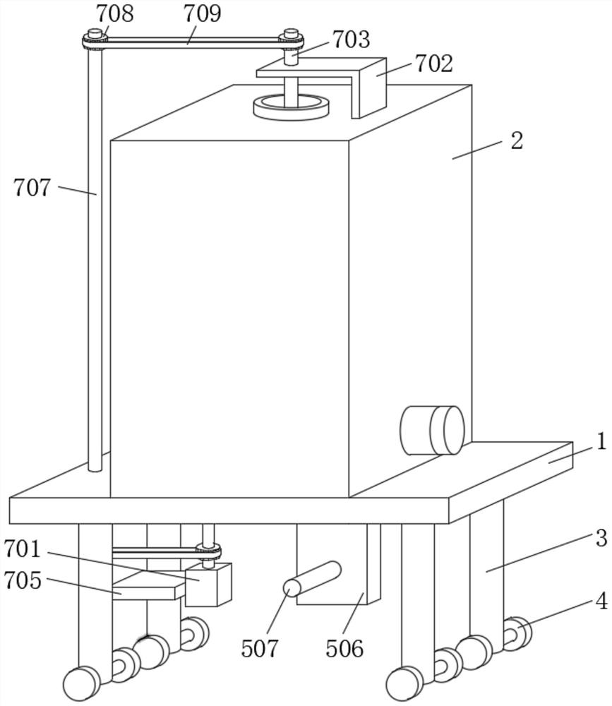
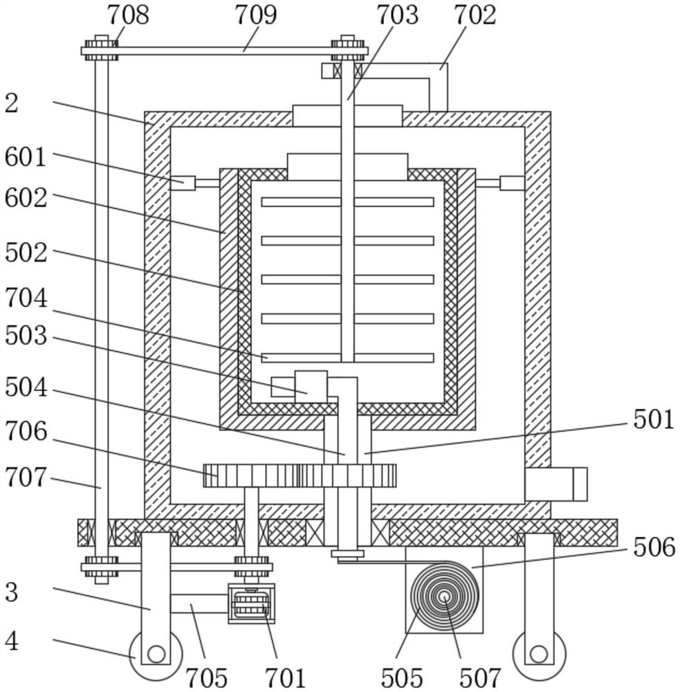
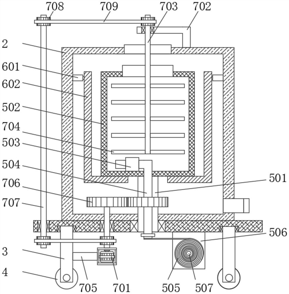
[0044] A mobile sludge filter press device comprises a base 1, a fixed box 2 is fixedly connected to the top of the base 1, a vertical rod 3 is symmetrically rotatably connected to both sides of the bottom of the base 1, and a rotating shaft is rotatably connected to the bottom end of the vertical rod 3, Both ends of the rotating shaft are fixed with rollers 4. A material collection mechanism is arranged between the base 1 and the fixed box 2. The material collection mechanism includes a cylindrical rod 501, a cylindrical box 502, a sludge pump 503 and a connecting pipe 504. The cylindrical rod 501 rotates Connected to the base 1, the cylindrical box 502 is fixed on the top of the cylindrical rod 501, the sludge pump 503 is arranged inside the cylindrical box 502, and the connecting pipe 504 is arranged on the sludge pump 503;

[0045] Specifically, the top of the fixed box 2 is provided with an opening, and the bottom of the right side of the fixed box 2 is provided with a wat...

Embodiment 2

[0062] A mobile sludge filter press device comprises a base 1, a fixed box 2 is fixedly connected to the top of the base 1, a vertical rod 3 is symmetrically rotatably connected to both sides of the bottom of the base 1, and a rotating shaft is rotatably connected to the bottom end of the vertical rod 3, Both ends of the rotating shaft are fixed with rollers 4. A material collection mechanism is arranged between the base 1 and the fixed box 2. The material collection mechanism includes a cylindrical rod 501, a cylindrical box 502, a sludge pump 503 and a connecting pipe 504. The cylindrical rod 501 rotates Connected to the base 1, the cylindrical box 502 is fixed on the top of the cylindrical rod 501, the sludge pump 503 is arranged inside the cylindrical box 502, and the connecting pipe 504 is arranged on the sludge pump 503;

[0063] Specifically, the top of the fixed box 2 is provided with an opening, and the bottom of the right side of the fixed box 2 is provided with a wat...


PUM


Abstract

The invention relates to the technical field of sludge treatment, and particularly discloses a movable sludge filter pressing device and a technological process thereof.The movable sludge filter pressing device comprises a base, a fixed box is fixedly connected to the top of the base, vertical rods are symmetrically and rotationally connected to the two sides of the bottom of the base, rotating shafts are rotationally connected to the bottom ends of the vertical rods, and rolling wheels are fixedly connected to the two ends of each rotating shaft; a material collecting mechanism is arranged between the base and the fixed box, and a leakage-proof mechanism is arranged in the fixed box; comprising the following steps: S1, moving equipment to a sewage plant; S2, collecting sludge; S3, disinfecting the sludge; S4, dehydrating the sludge; according to the sludge treatment device, the motor, the long shaft, the cylindrical rod, the vertical shaft and the belt are arranged, so that the rotating directions of the cylindrical box and the vertical shaft are opposite, a stirring shaft on the vertical shaft can fully stir and make contact with sludge and a treatment solvent in the cylindrical box, and limestone is added to treat harmful substances in the sludge; by adding cationic polyacrylamide (PAM < + >), the sludge dewatering efficiency can be realized.

Description

technical field [0001] The invention relates to the technical field of sludge treatment, in particular to a mobile sludge filter press device and its technological process. Background technique [0002] Daily life and factories will produce a large amount of sludge. The sludge contains debris and bacteria. It is easy to pollute the environment and cause harm to the human body if it is discharged into the environment. Therefore, it is necessary to treat the sludge to ensure that people can live a better life and Production. [0003] At present, the sewage stations in various regions are built at an early age and the equipment is outdated. At the same time, due to the lack of sites near the sewage plant, a sludge dewatering system cannot be added; the existing sludge treatment effect is poor, and some areas and units It is not economical to build a new sludge dewatering system, increases a lot of manufacturing costs, and is not practical. [0004] Based on this, the present ...

Claims


Application Information

Patent Timeline
Patent Type & Authority Applications(China)
IPC IPC(8): C02F11/122C02F11/00C02F11/147B01F27/90B01F35/30B01D29/82B01D29/35B30B9/06
CPCC02F11/122C02F11/147C02F11/004B01D29/35B01D29/82B30B9/06
Inventor 仲海玲杨春燕高勇何健高博
Owner 华夏中然生态科技集团有限公司
Learn More