Rainwater collecting and irrigating system for municipal roads

A rainwater collection and irrigation system technology, applied in general water supply conservation, watering devices, water supply devices, etc., can solve problems such as removal of leaves or other impurities, lack of diversion, and clogging of irrigation systems to avoid damage to greenery , the effect of improving practicality and relieving discharge pressure

Pending Publication Date: 2022-07-05
杨凤娥
View PDF8 Cites 0 Cited by
  • Summary
  • Abstract
  • Description
  • Claims
  • Application Information

AI Technical Summary

Problems solved by technology

[0003] 1. The existing municipal road rainwater collection irrigation system cannot remove the leaves or other impurities mixed in the rainwater, which will easily lead to blockage of the irrigation system and is not practical;
[0004] 2. The existing municipal road rainwater collection irrigation system, sometimes due to the excessive rainwater, the rainwater collection is slow and does not have the function of diversion

Method used


Image

  • Rainwater collecting and irrigating system for municipal roads
  • Rainwater collecting and irrigating system for municipal roads
  • Rainwater collecting and irrigating system for municipal roads

Examples


Embodiment 1

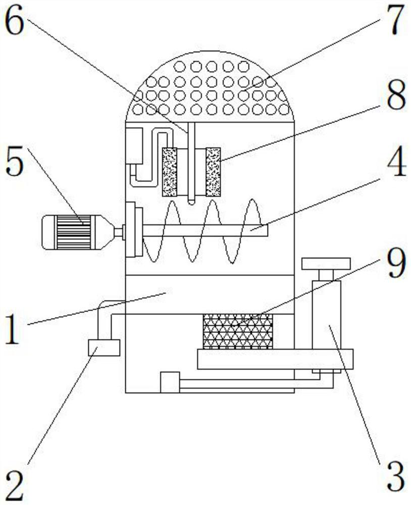
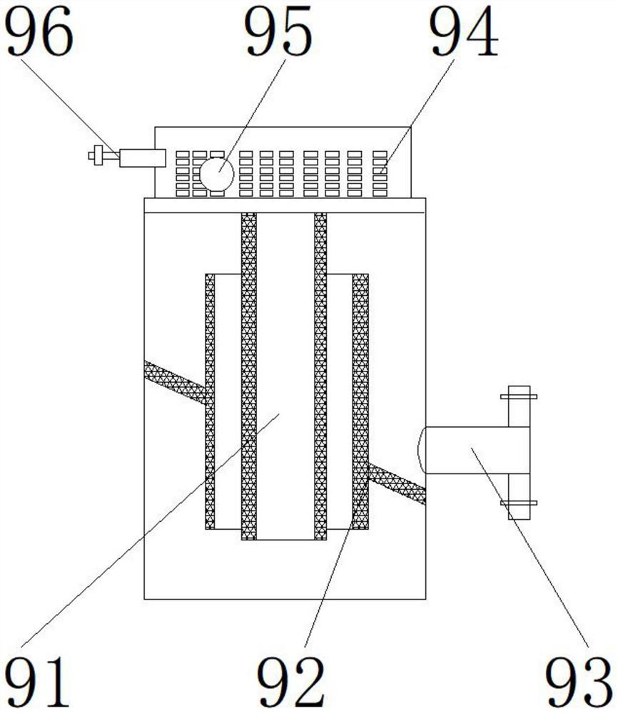
[0027] like Figure 1-5 As shown in the figure, the present invention provides a municipal road rainwater collection and irrigation system, comprising a main body 1, an impurity removing device 4 is arranged above the main body 1, a motor 5 is arranged on one side of the impurity removing device 4, and a top of the impurity removing device 4 is arranged There is a water storage tank 8, the upper end of the water storage tank 8 is provided with a diversion device 6, the upper end of the diversion device 6 is provided with a mesh 7, the lower end of the main body 1 is provided with a filter device 9, and one side of the main body 1 is provided with a discharge pipe 2, One side of the filter device 9 is provided with a water pump 3; the filter device 9 includes a filter element 91, a filter screen 92, a water outlet pipe 93, a separation cavity 94, a floating ball device 95, and a ball valve 96, and the filter screen 92 is located on both sides of the filter element 91. The water...

Embodiment 2

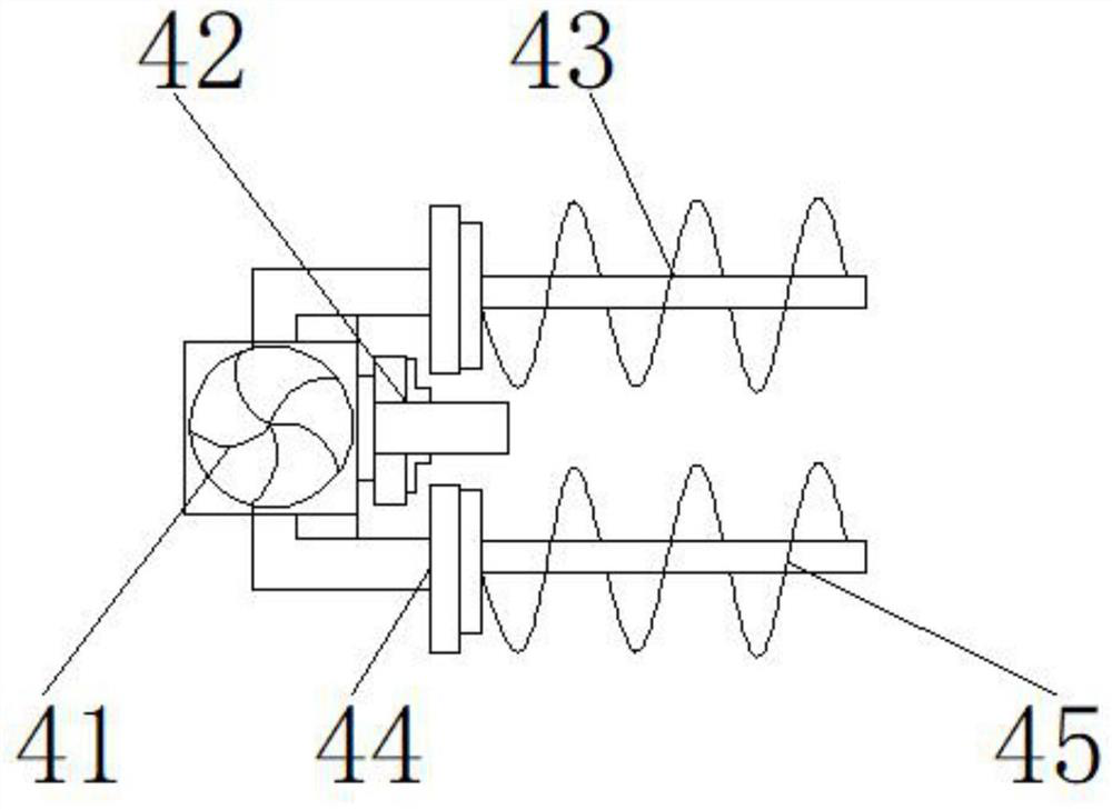
[0030] like Figure 1-5 As shown, on the basis of Embodiment 1, the present invention provides a technical solution: preferably, the impurity removal device 4 includes a driving device 41, a movable plate 42, a rotating roller 43, a bearing 44, and a scraper 45, and the movable plate 42 is located in the On one side of the driving device 41, the bearing 44 is located above and below the movable plate 42, the rotating roller 43 is located on one side of the bearing 44, the scraper 45 is located on the outer surface of the rotating roller 43, and a connecting shaft is provided between the driving device 41 and the bearing 44 , the lower end of the driving device 41 is fixedly connected to one side of the bearing 44 through the connecting shaft, a threaded groove is provided between the bearing 44 and the rotating roller 43, and the other side of the bearing 44 is detachably connected to one side of the rotating roller 43 through the thread groove A welding block is arranged betw...

Embodiment 3

[0033] like Figure 1-5 As shown, on the basis of Embodiment 1, the present invention provides a technical solution: preferably, the shunt device 6 includes a branch pipe 61, a shunt pipe 62, a pipeline 63, a rocker lever 64, and an auxiliary device 65, and the shunt pipe 62 is located in the branch pipe. At the lower end of 61, the rocker lever 64 is located at one side of the pipe 63, the auxiliary device 65 is located at the upper end of the rocker lever 64, the pipe 63 is located at the lower end of the rocker lever 64, a connecting hole is provided between the branch pipe 61 and the branch pipe 62, and the branch pipe The lower end of 61 is fixedly connected to the upper end of the shunt pipe 62 through the connecting hole, an interface is provided between the shunt pipe 62 and the rocker arm rod 64, one side of the rocker arm rod 64 is fixedly connected to one side of the shunt pipe 62 through the interface, and the rocker arm A notch is provided between the rod 64 and t...


PUM


Abstract

The invention discloses a municipal road rainwater collection and irrigation system, and relates to the technical field of rainwater collection and irrigation, the municipal road rainwater collection and irrigation system comprises a main body, an impurity removal device is arranged above the main body, a motor is arranged on one side of the impurity removal device, a water storage tank is arranged above the impurity removal device, and a diversion device is arranged at the upper end of the water storage tank; meshes are formed in the upper end of the flow dividing device, and a filtering device is arranged at the lower end of the main body. Under the combined action of a driving device, a movable plate, a rotating roller, a bearing and a scraping piece, large-size object garbage such as leaves doped in rainwater can be effectively removed, an irrigation system is prevented from being blocked, and under the combined action of a branch pipe, a flow dividing pipe, a pipeline, a rocker arm rod, a disc, a partition plate, a water inlet hole, a cover plate and a connecting pipe, the rainwater can be effectively removed. The situation that rainwater collection is slow due to too large rainfall can be avoided, rainwater can be collected and conveyed in a flow dividing mode, and therefore the practicability of the irrigation system is improved.

Description

technical field [0001] The invention relates to the technical field of rainwater collection and irrigation, in particular to a municipal road rainwater collection and irrigation system. Background technique [0002] With the further rapid development of the national economy, urban construction has also entered a new historical stage, which has gradually transitioned from the previous function only to the combination of function, landscape and ecology. Municipal road greening refers to planting trees, flowers and forests on both sides of the road and in the separation zone to achieve the purpose of isolating noise, purifying the air and beautifying the environment. As the artery of urban infrastructure, road greening occupies a relatively heavy weight. Road greening can not only play a role in ecological protection, form green belt isolation, form a linear urban green landscape, but also create a more suitable life for the general public. Therefore, the municipal road greeni...

Claims


Application Information

Patent Timeline
Patent Type & Authority Applications(China)
IPC IPC(8): A01G25/00B01D36/00E03B3/02
CPCA01G25/00E03B3/02B01D36/00Y02A20/108
Inventor 杨凤娥
Owner 杨凤娥
Why Eureka
Try Eureka