
Vernier sensitization optical fiber air pressure sensor combined with coating technology and preparation method of vernier sensitization optical fiber air pressure sensor

A technology of air pressure sensor and optical fiber, which is applied in fluid pressure measurement using optical methods, cladding optical fiber, instruments, etc., can solve the problem of low air pressure sensitivity, and achieve the effects of easy preparation, low preparation technical requirements, and great application potential

Pending Publication Date: 2022-07-05
HEILONGJIANG UNIV
View PDF0 Cites 0 Cited by
  • Summary
  • Abstract
  • Description
  • Claims
  • Application Information

AI Technical Summary

Problems solved by technology

However, the existing closed-cavity optical fiber air pressure sensor has the defect of low air pressure sensitivity

Method used


Image

  • Vernier sensitization optical fiber air pressure sensor combined with coating technology and preparation method of vernier sensitization optical fiber air pressure sensor
  • Vernier sensitization optical fiber air pressure sensor combined with coating technology and preparation method of vernier sensitization optical fiber air pressure sensor
  • Vernier sensitization optical fiber air pressure sensor combined with coating technology and preparation method of vernier sensitization optical fiber air pressure sensor

Examples


specific Embodiment approach 1

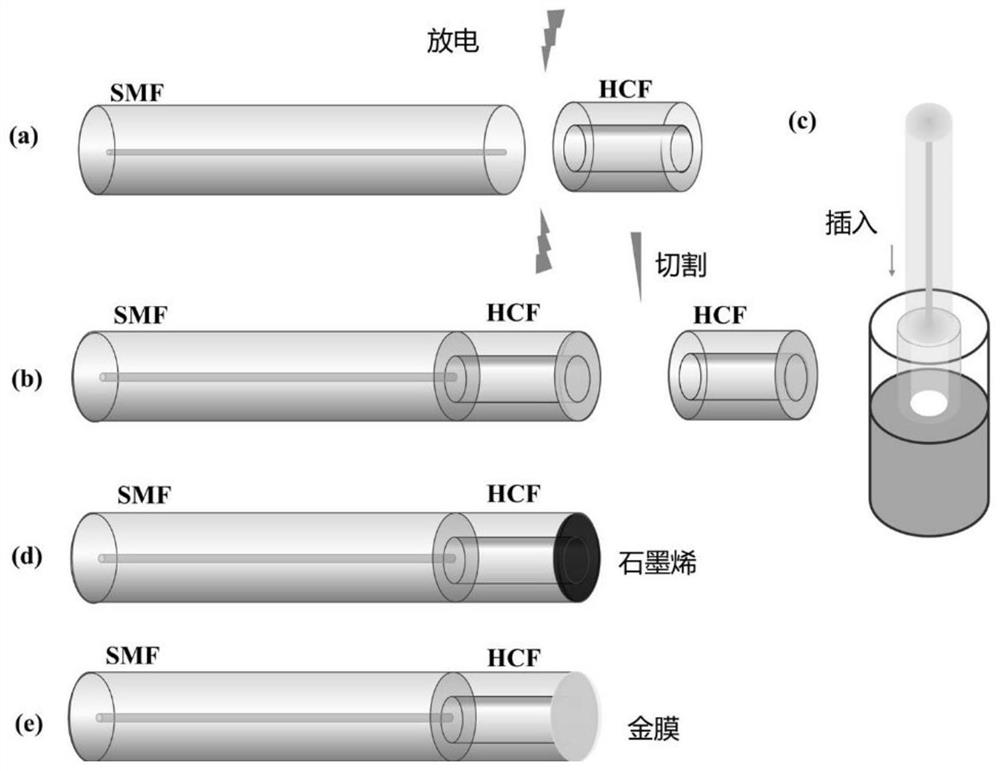
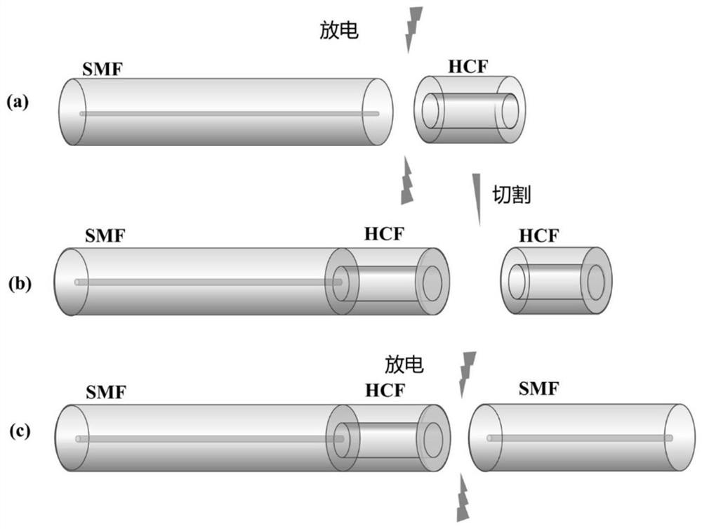
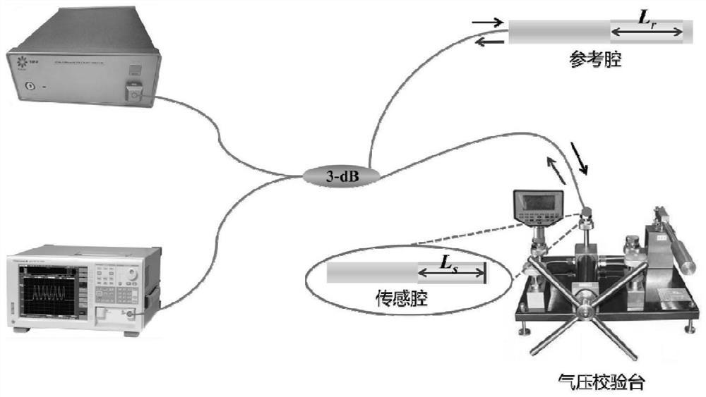
[0028] Embodiment 1: The vernier-sensitized optical fiber air pressure sensor combined with the coating technology in this embodiment includes a broadband light source, a spectrum analyzer and a 3-dB coupler, as well as a microcavity FPI-1 and a microcavity FPI-2;

[0029] Among them, the output end of the broadband light source and the input end of the spectrum analyzer are respectively connected to one port of the 3dB coupler through an optical fiber; the microcavity FPI-1 and the microcavity FPI-2 are connected in parallel and are respectively connected to the two ports of the 3dB coupler through an optical fiber ;

[0030] The microcavity FPI-1 is made by splicing one end of a single-mode fiber with a flat end face and a hollow core fiber with a flat end face, and the other end of the hollow core fiber is sequentially coated with graphene oxide film and gold film to seal the hollow core fiber;

[0031] The microcavity FPI-2 is made of two single-mode fibers and a hollow-co...

specific Embodiment approach 2

[0050] Embodiment 2: The difference between this embodiment and Embodiment 1 is that: L s 157μm, L r is 166 μm. Other steps and parameters are the same as in the first embodiment.

specific Embodiment approach 3

[0051] Specific embodiment three: the preparation method of the cursor-sensitized optical fiber air pressure sensor combined with the coating technology in this embodiment:

[0052] A. Preparation of microcavity FPI-1

[0053] A-1. Peel off the coating of the hollow core fiber and single-mode fiber, and wipe the coated single-mode fiber and hollow-core fiber with non-woven fabric dipped in alcohol repeatedly in one direction, and then use a fiber cleaver Cut the end faces of single-mode fibers and hollow-core fibers flat;

[0054] A-2. Weld the flattened end face of the single-mode fiber with the flattened end face of the hollow core fiber, and then keep the length of the hollow core fiber as L s , cut the other end face of the hollow-core fiber flat, and then coat it with a graphene oxide film;

[0055] A-3. Coating gold film on the outside of graphene oxide film;

[0056] B. Preparation of microcavity FPI-2: peel off the coating of the hollow-core fiber and the two-segmen...


PUM

PropertyMeasurementUnit
Outer diameteraaaaaaaaaa
Diameteraaaaaaaaaa
Inner diameteraaaaaaaaaa

Abstract

The invention relates to an optical fiber baroceptor and a preparation method thereof, in particular to a vernier sensitization optical fiber baroceptor combined with a coating technology and a preparation method of the vernier sensitization optical fiber baroceptor. The invention relates to a vernier sensitization optical fiber barometric sensor combined with a coating technology. The vernier sensitization optical fiber barometric sensor comprises a broadband light source, a spectrum analyzer, a 3-dB coupler, a microcavity FPI-1 and a microcavity FPI-2. The preparation method comprises the following steps: A, preparing the microcavity FPI-1; b, a microcavity FPI-2 is prepared; and C, connecting the micro-cavity FPI-1 and the micro-cavity FPI-2 in parallel, respectively connecting the micro-cavity FPI-1 and the micro-cavity FPI-2 with two ports of a 3dB coupler through optical fibers, and respectively connecting the output end of the broadband light source and the input end of the spectrum analyzer with one port of the 3dB coupler through optical fibers. The sensitivity of the vernier sensitization optical fiber barometric sensor combined with the coating technology is 22.98 times that of a single air cavity optical fiber barometric sensor, and the sensitivity of air pressure detection is greatly improved.

Description

technical field [0001] The invention relates to an optical fiber air pressure sensor and a preparation method thereof. Background technique [0002] Optical fiber air pressure sensors have been widely used in automated production, aerospace, military and medical diagnostic fields due to their compactness, anti-interference and high precision. Various fiber-optic sensors, such as long-period fiber gratings, fiber Bragg gratings, Mach-Zehnder interferometers, and Fabry-Perot interferometers (FPIs) have been developed to measure gas pressure, among which FPIs are It is very promising because of its simplicity and convenient combination. [0003] Optical fiber FP cavity sensor has the advantages of high sensitivity, small size, simple structure, fast response, anti-electromagnetic interference, etc., and has received extensive attention from all walks of life. In order to improve the problem of low air pressure sensitivity of a single closed-cavity optical fiber air pressure s...

Claims


Application Information

Patent Timeline
IPC IPC(8): G01L11/02G01L19/00G02B6/02
CPCG01L11/025G01L19/00G02B6/02
Inventor 冉玲苓宋小康杨九如李唱石丽慧马云鹏
Owner HEILONGJIANG UNIV
Learn More