AI visual inspection equipment and system for shell structure defect detection

A technology of visual inspection and shell structure, applied in the field of visual inspection, can solve the problems of incomplete inspection of all sides of the product, large space of inspection equipment, and easy deviation of rotation angle, so as to achieve simple and fast transmission direction change and avoid operation. The effect of many processes and less difficulty in process production

Active Publication Date: 2022-07-05
中信云网有限公司 +1
View PDF8 Cites 0 Cited by
  • Summary
  • Abstract
  • Description
  • Claims
  • Application Information

AI Technical Summary

Problems solved by technology

[0004] However, when it is necessary to detect multiple surfaces of a shell structure product (for example, a notebook shell or a mobile phone shell) at the same time, the existing visual inspection equipment is often difficult At the same time, taking into account the detection efficiency and the accuracy of the detection results
For example, some detection methods in the prior art are to fix a certain surface of the product on the carrier platform, and detect each panel of the product by moving the detection device (such as a camera). Occupies a lot of space, and the detection of all sides of the product is not comprehensive. Of course, there are some detection methods that rotate the product in the vertical plane or horizontal plane, so as to visually detect all sides of the product, for example, patent announcements The invention patent No. CN111896552A discloses a new type of notebook casing defect detection equipment, and the invention patent No. CN113670923A discloses a comprehensive high-precision detection device and method for notebook computer casing defects. All-round inspection of the shell structure, but at least the following shortcomings:
[0005]1) The cost of automation is high, and the rotating structure used for rotating products in existing inspection equipment is relatively complicated (such as including multiple rotating shafts for rotating), correspondingly Increase the production cost and operating cost of the detection equipment, and this type of detection equipment has poor stability in the actual operation process (for example, the rotating structure is prone to wear and tear after working for a long time, and it is difficult to maintain working stability) and poor accuracy (for example, rotating The angle is prone to deviation), and if higher stability and accuracy requirements are required for the detection equipment, it will further increase the automation cost of the equipment;
[0006]2) The beat of the production line is slow. Due to the need to rotate a single product, it takes a long time to shoot and detect a single product, and the operation required for a single station More (for example, taking multiple photos with a single camera), it is difficult to meet the production line beat requirements. In addition, the invention patent with the patent announcement number of CN113670923A is mainly for the detection of shell defects for the whole notebook, and in the current actual application scenario , the production line takt requirements for the whole notebook machine detection are relatively low, for example, a single detection of the whole notebook machine takes only ten or twenty seconds, and correspondingly, the operation time of a single station of the testing equipment is relatively long However, in order to meet the production needs, the production line beat requirements for the detection of the notebook shell structure (not the whole machine structure) are relatively high. Therefore, the existing testing equipment often cannot meet the production line requirements for the notebook shell structure in actual work. Tempo requirements;
[0007] 3) Poor compatibility. The shell structure produced by raw material manufacturers usually has many types of defects. For some special types of defects, or defects located in specific positions, only the side image or appearance image of the shell structure may not be clearly identified corresponding defects
For example, only acquiring the side image or appearance surface image of the shell may not be able to identify the defects at the corners of the shell (that is, the intersection of two adjacent sides of the shell), so it is necessary to The angle is taken separately, which involves adjusting the rotation angle of the rotating mechanism / module, which will further increase the structural complexity of the rotating mechanism / module and affect the stability of the equipment; that is to say, the detection equipment has a single function, Poor compatibility, it can only be tested for the shell structure of the current model. If you need to test shell structures with different materials, types, colors, and characteristics, you will need to test the light source, lens, camera, acquisition card, image processing software, The controller, communication unit, etc. are replaced or modified, and the operation is complicated;
[0008]4) Since the rotating structure of the testing equipment is relatively complex, the volume of the corresponding rotating structure is relatively large, so the overall floor space of the testing equipment is relatively large

Method used


Image

  • AI visual inspection equipment and system for shell structure defect detection
  • AI visual inspection equipment and system for shell structure defect detection
  • AI visual inspection equipment and system for shell structure defect detection

Examples


Embodiment 1

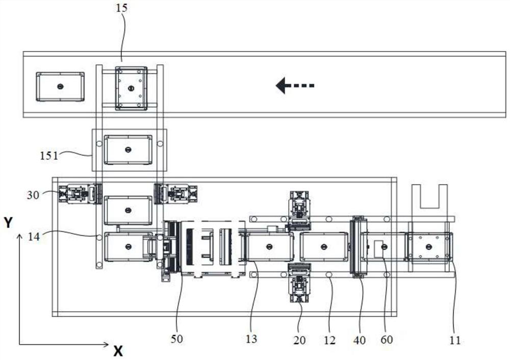
[0069] Please refer to Figure 1-Figure 9 , AI visual inspection equipment, including:

[0070] Transmission structure, one end of the transmission structure is the material loading position 11, the other end of the transmission structure is the material lowering position 15, the transmission structure has a transmission position for the housing structure to move, and the transmission position includes: a first The transmission segment and the second transmission segment, and the transmission directions of the first transmission segment and the second transmission segment are different;

[0071] Two first side visual detection devices 20, two of the first side visual detection devices 20 are respectively arranged on both sides of the first transmission section of the transmission position;

[0072] Two second side visual detection devices 30, two of the second side visual detection devices 30 are respectively arranged on both sides of the second transmission section of the tr...

Embodiment 2

[0130] Based on the AI ​​visual inspection device in the above embodiment, the present invention further provides an AI visual inspection system, including an industrial computer, a quality inspection server, and the aforementioned AI visual inspection device;

[0131] The industrial computer is connected to the AI ​​visual inspection device to control the AI ​​visual inspection device and receive inspection information, and the industrial computer is wired or wirelessly connected to the quality inspection server to transmit inspection information and obtain identification result.

[0132] The industrial computer is responsible for scheduling each device to take pictures, uploading the pictures to the quality inspection server, calling the algorithm model and rule processing program deployed on the quality inspection server to identify and determine the defects, and finally send the identification results returned by the service to The industrial computer controls the correspo...


PUM


Abstract

The invention relates to the technical field of visual inspection, and provides AI visual inspection equipment and system for shell structure defect detection. The AI visual inspection equipment comprises a transmission structure, one end of the transmission structure is a feeding position, the other end of the transmission structure is a discharging position, the transmission structure is provided with a transmission position for products to move, and the transmission position comprises a first transmission section and a second transmission section which are different in transmission direction; the at least two first side surface visual detection devices are respectively arranged on two sides of the first transmission section; the at least two second side surface visual detection devices are respectively arranged on two sides of the second transmission section; the structural surface visual detection device is arranged below the transmission position; and the appearance surface visual detection device is arranged above the transmission position. The AI visual inspection equipment provided by the invention realizes all-around rapid visual inspection of products.

Description

technical field [0001] The present invention relates to the technical field of visual inspection, in particular to an AI visual inspection device and an AI visual inspection system used for the detection of shell structure defects. Background technique [0002] Visual inspection refers to measuring and judging by machines instead of human eyes. In practical applications, visual inspection can realize surface defect detection of production products, and with years of development, this technology has become very mature. [0003] In the process of intelligent manufacturing, the image of the objective object is taken by the camera with the aid of the lens and the light source, and then the image is collected by the capture card and stored in the computer or server hard disk, and the image processing software uses the rule algorithm to segment the image. , After the calculation, a certain result is obtained, and the result is used for the detection, measurement and control of the...

Claims


Application Information

Patent Timeline
Patent Type & Authority Applications(China)
IPC IPC(8): G01N21/89G01N21/01G01N21/13
CPCG01N21/8901G01N21/8903G01N21/01G01N21/13G01N2021/0112Y02P90/30
Inventor 肖刚袁卫顺何勃葛履李作维
Owner 中信云网有限公司
Why Eureka
Try Eureka