Permanent magnet motor and use method thereof

A technology of permanent magnet motors and bodies, applied in the direction of motors, electric components, electric vehicles, etc., can solve the problems of motor efficiency reduction, temperature rise, turbulence, etc., to achieve the effect of ensuring cooling effect, improving cooling efficiency, and preventing demagnetization

Pending Publication Date: 2022-07-05
俞燕明
View PDF0 Cites 0 Cited by
  • Summary
  • Abstract
  • Description
  • Claims
  • Application Information

AI Technical Summary

Problems solved by technology

[0004] When the existing permanent magnet motor is in use, it is necessary to prevent external dust from entering the body, causing pollution to the position between the rotor and the stator, resulting in blocked rotation, and the body needs to be set in a sealed state. At this time, the internal temperature of the body will rise. It is also difficult to control the temperature below 60 degrees Celsius when the fan cooperates with the heat sink to cool down. When the temperature is higher than 60 degrees Celsius, the magnetic force of the permanent magnet will decrease at this time, resulting in demagnetization. Although this demagnetization phenomenon is reversible (after a period of time after the temperature drops The magnetic force can be restored), but the demagnetization during the operation of the motor will reduce the efficiency of the motor and affect its use, and the external vibration will also cause the internal magnetic poles of the permanent magnet to fluctuate and cause demagnetization. At the same time, when the motor is at a lower temperature When the environment is used, the internal temperature of the motor decreases at this time, which increases the magnetic force of the permanent magnet. At this time, the current through the motor increases, causing the motor to run with super power, which is easy to cause damage to the motor components, and the excessive current will also cause the permanent magnet to demagnetize with high current. , so there is an urgent need for a motor to solve the above problems

Method used


Image

  • Permanent magnet motor and use method thereof
  • Permanent magnet motor and use method thereof
  • Permanent magnet motor and use method thereof

Examples


Embodiment Construction

[0031] The technical solutions in the embodiments of the present invention will be clearly and completely described below with reference to the accompanying drawings in the embodiments of the present invention. Obviously, the described embodiments are only a part of the embodiments of the present invention, but not all of the embodiments. Based on the embodiments of the present invention, all other embodiments obtained by those of ordinary skill in the art without creative efforts shall fall within the protection scope of the present invention.

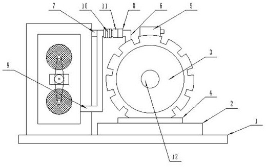
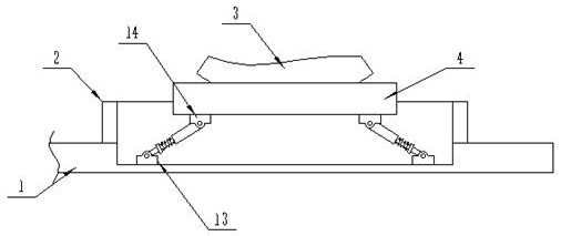
[0032] see Figure 1-10 , The present invention provides a technical solution: a permanent magnet motor, comprising a bottom plate 1 and a body 3, a hollow block 2 is fixedly arranged at the top of the bottom plate 1, and a movable plate 4 is arranged inside the hollow block 2 for movable clamping, and the movable A body 3 is fixedly arranged at the top of the plate 4, an output shaft 12 is arranged at the output end of the body 3, a ...


PUM


Abstract

The motor comprises a bottom plate and a machine body, a hollow block is fixedly arranged at the top end of the bottom plate, a movable plate is movably clamped in the hollow block, the machine body is fixedly arranged at the top end of the movable plate, an output shaft is arranged at the output end of the machine body, and a buffer mechanism is arranged between the movable plate and the bottom end of the hollow block. A junction box is fixedly arranged at the top end of the machine body, a first pipeline is fixedly arranged at the top end of the machine body, a cooling mechanism is arranged at the top end of the bottom plate, and a power mechanism is arranged on one side of the machine body. When a power supply is connected, a connector is aligned with a slot, then an insertion block is inserted into the slot, a sleeve is rotated to sleeve the outer side wall of the slot, the sleeve is rotated to move towards the left side, a third spring is extruded and compressed at the moment, the third spring extrudes the insertion block through elastic force, the insertion block is tightly attached to the inner side of the slot, and the power supply is connected. Connectivity is ensured, and poor contact of connection positions is prevented.

Description

technical field [0001] The invention relates to the field of permanent magnet motor equipment, in particular to a permanent magnet motor and a method of using the same. Background technique [0002] Motor (English: Electric machinery, commonly known as "motor") refers to an electromagnetic device that realizes the conversion or transmission of electrical energy according to the law of electromagnetic induction. [0003] The motor is represented by the letter M (the old standard is D) in the circuit. Its main function is to generate driving torque. As a power source for electrical appliances or various machinery, the generator is represented by the letter G in the circuit. The function is to convert mechanical energy into electrical energy, and the motor rotor is made of permanent magnet material, which is a permanent magnet motor. The permanent magnet motor can make the rotor rotate without installing an excitation coil on the rotor, thereby saving resources and electrical e...

Claims


Application Information

Patent Timeline
IPC IPC(8): H02K5/20H02K9/19H02K9/22H02K5/24H02H7/085
CPCH02K5/203H02K9/19H02K9/227H02K5/24H02H7/085Y02T10/64
Inventor 俞燕明
Owner 俞燕明
Why Eureka
Try Eureka