
Annular steel pipe automatic welding device with welding auxiliary system

An automatic welding and auxiliary system technology, applied in auxiliary devices, welding/cutting auxiliary equipment, welding equipment, etc., can solve problems such as the impact of spring installation accuracy and service life, reducing the use limitations of welding devices, and reducing user convenience. , to achieve a wide range of applications, reduce the number of replacement of different fixed structures, and improve the effect of diversity

Inactive Publication Date: 2022-07-08
GUILIN UNIV OF AEROSPACE TECH
View PDF1 Cites 2 Cited by
  • Summary
  • Abstract
  • Description
  • Claims
  • Application Information

AI Technical Summary

Problems solved by technology

[0004] Although the purpose of positioning the steel pipe is achieved through the cooperation between the workpieces, the cooperation between the various workpieces is relatively cumbersome. Although the purpose of fixing steel pipes of different sizes can be achieved, the positioning of larger objects is carried out through elastic elements such as springs. The installation accuracy will have a great impact on its service life. At the same time, after long-term use, the elastic potential energy of the spring will weaken, and the fixing effect will also weaken. It is not easy to replace it, which reduces the use limitation of the welding device to a certain extent. , also reduces the user's convenience of operation, and secondly, the welded steel pipe needs a long cooling time, and when the steel pipe is placed on the welding device, the follow-up welding work cannot be carried out, which consumes resources and wastes time. Its forced removal will not only cause the quality of steel pipe welding to decline, but also may cause safety accidents, threatening the personal health of users

Method used


Image

  • Annular steel pipe automatic welding device with welding auxiliary system
  • Annular steel pipe automatic welding device with welding auxiliary system
  • Annular steel pipe automatic welding device with welding auxiliary system

Examples


Embodiment Construction

[0029] The technical solutions in the embodiments of the present invention will be clearly and completely described below with reference to the accompanying drawings in the embodiments of the present invention. Aspects of the invention are described in this disclosure with reference to the accompanying drawings, in which a number of illustrative embodiments are shown. It should be understood that the various concepts and embodiments presented above, as well as those concepts and implementations described in greater detail below, can be implemented in any of numerous ways. Based on the embodiments of the present invention, all other embodiments obtained by those of ordinary skill in the art without creative efforts shall fall within the protection scope of the present invention.

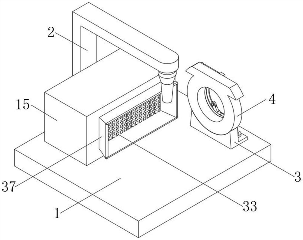
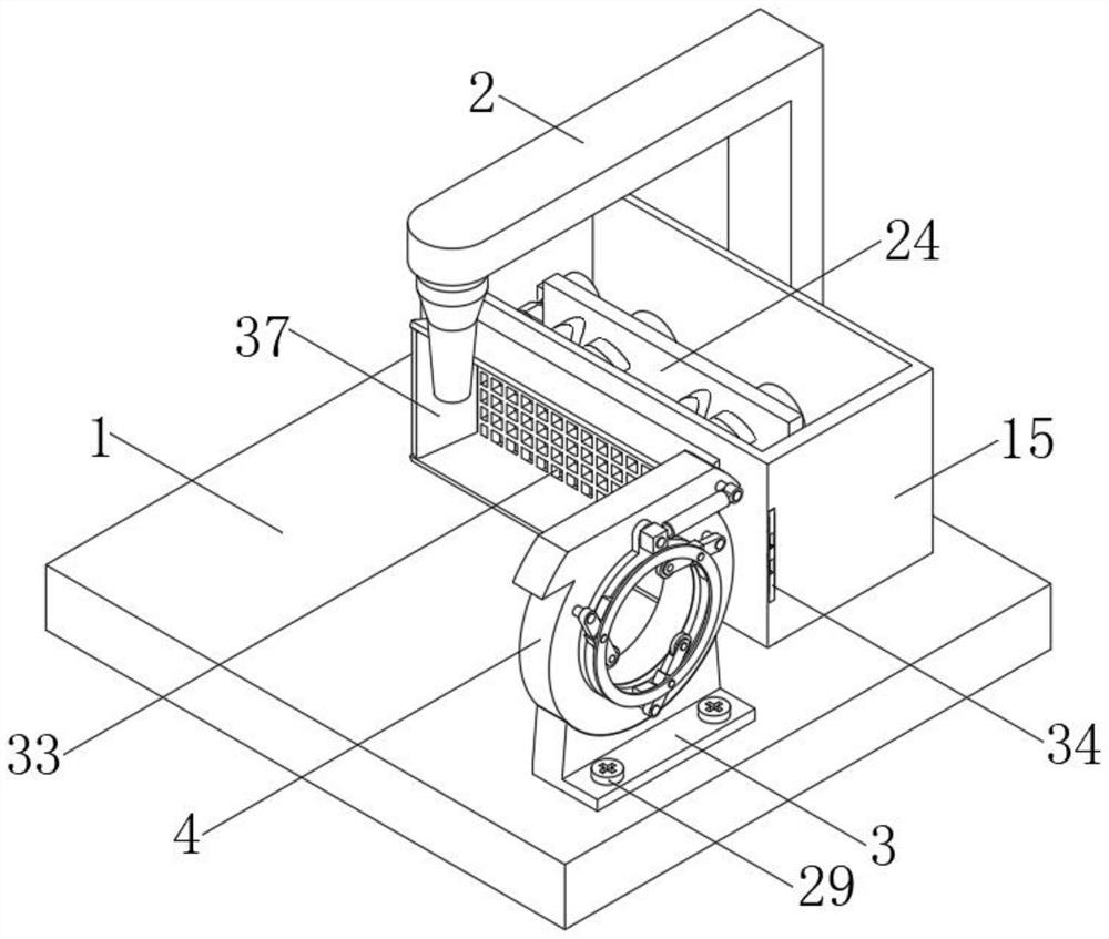
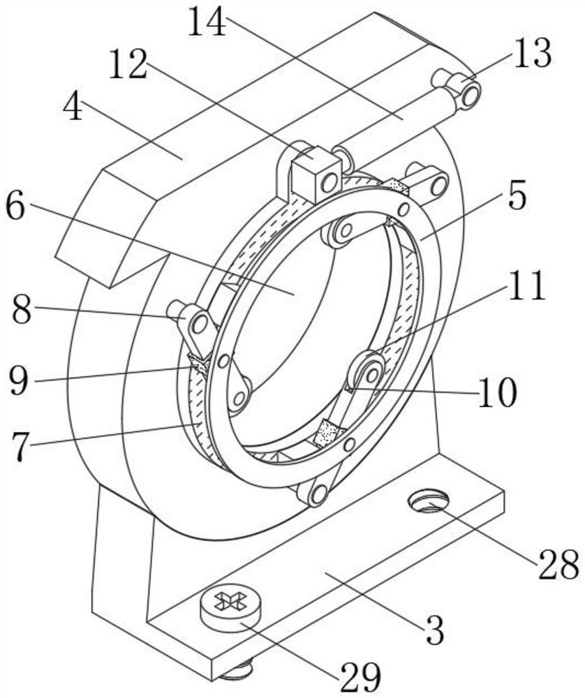
[0030] as attached figure 1 to the attached Figure 7Shown: This embodiment provides an automatic welding device for annular steel pipes with a welding auxiliary system, including: a base 1 and a we...


PUM


Abstract

The invention relates to the technical field of welding, in particular to an annular steel pipe automatic welding device with a welding auxiliary system.The annular steel pipe automatic welding device comprises a base and welding equipment, the welding equipment is located at the top of the base and fixedly connected with the base, a mounting part is arranged on the right side of the top of the base, and a fixing part is fixedly connected to the top of the mounting part; a rotating disc is arranged on the right side of the fixing piece, and clamping cavities are formed in one side of the fixing piece and one side of the rotating disc. The automatic annular steel pipe welding device with the welding auxiliary system has the advantages of being adjustable in size, wide in application range and high in cooling speed, in the actual using process, a fixing structure is additionally arranged on the surface of the welding device firstly, so that the automatic annular steel pipe welding device adapts to annular steel pipe structures of different sizes, the using diversity of the device is improved, and the using cost is reduced. The use range is expanded, meanwhile, the frequency of replacing different fixing structures by a user is reduced, and the operation time is saved.

Description

technical field [0001] The invention relates to the technical field of welding, in particular to an automatic welding device for annular steel pipes with a welding auxiliary system. Background technique [0002] Welding, also known as welding, is a manufacturing process and technique for joining metals or other thermoplastic materials such as plastics by heat, high temperature, or high pressure. [0003] An automatic auxiliary positioning welding system for steel pipe furniture disclosed in Publication No. CN 213163941 U. The beneficial effect achieved by the application is that a mobile base is set for the automatic auxiliary positioning welding system for steel pipe furniture, so that the staff can be in the process of steel pipe welding. According to the processing requirements, the welding position of the steel pipe can be flexibly moved, which is convenient for the welding process of the device, improves the welding efficiency of the device, and promotes the suitable ra...

Claims


Application Information

Patent Timeline
Patent Type & Authority Applications(China)
IPC IPC(8): B23K37/053B23K37/00B23K101/06
CPCB23K37/0533B23K37/003B23K2101/06
Inventor 刘运强叶东宋小辉
Owner GUILIN UNIV OF AEROSPACE TECH
Learn More