Automatic formwork erecting and withdrawing driving device and intelligent control method

A driving device and ejection technology, which is applied in the erection/assembly of bridges, bridges, buildings, etc., can solve problems such as the inability to reduce the risk of high-altitude operations, the labor force of construction personnel, and the heavy weight of large formwork, so as to improve construction safety and simplify construction. Structure, cost-effective effect

Pending Publication Date: 2022-07-08
CCCC WUHAN HARBOR ENG DESIGN & RES
View PDF1 Cites 0 Cited by
  • Summary
  • Abstract
  • Description
  • Claims
  • Application Information

AI Technical Summary

Problems solved by technology

However, the formwork construction process of pier columns, towers and other structures is mostly at high altitude, and the large formwork is heavy in weight, the construction personnel are labor intensive, and the construction risk is relatively large
Prior art also has the scheme that adopts formwork trolley to carry out formwork construction, for example CN104533456A records a kind of method for reinforced concrete formwork construction of super-large section chamber, adopts hydraulic oil cylinder and screw jack to adjust formwork to be in place and close formwork, involves in this method The structure is difficult to be used in high-altitude construction
Moreover, the formwork trolley uses hydraulic cylinders and screw jacks to adjust the formwork in place and close the formwork, which only realizes mechanized operations, and requires manual operations by construction personnel on site, including assembling and adjusting formwork, operating control handles, etc., which does not reduce the impact on pier columns The risk of working at heights during the construction of structures such as towers and towers

Method used


Image

  • Automatic formwork erecting and withdrawing driving device and intelligent control method
  • Automatic formwork erecting and withdrawing driving device and intelligent control method
  • Automatic formwork erecting and withdrawing driving device and intelligent control method

Examples


Embodiment 1

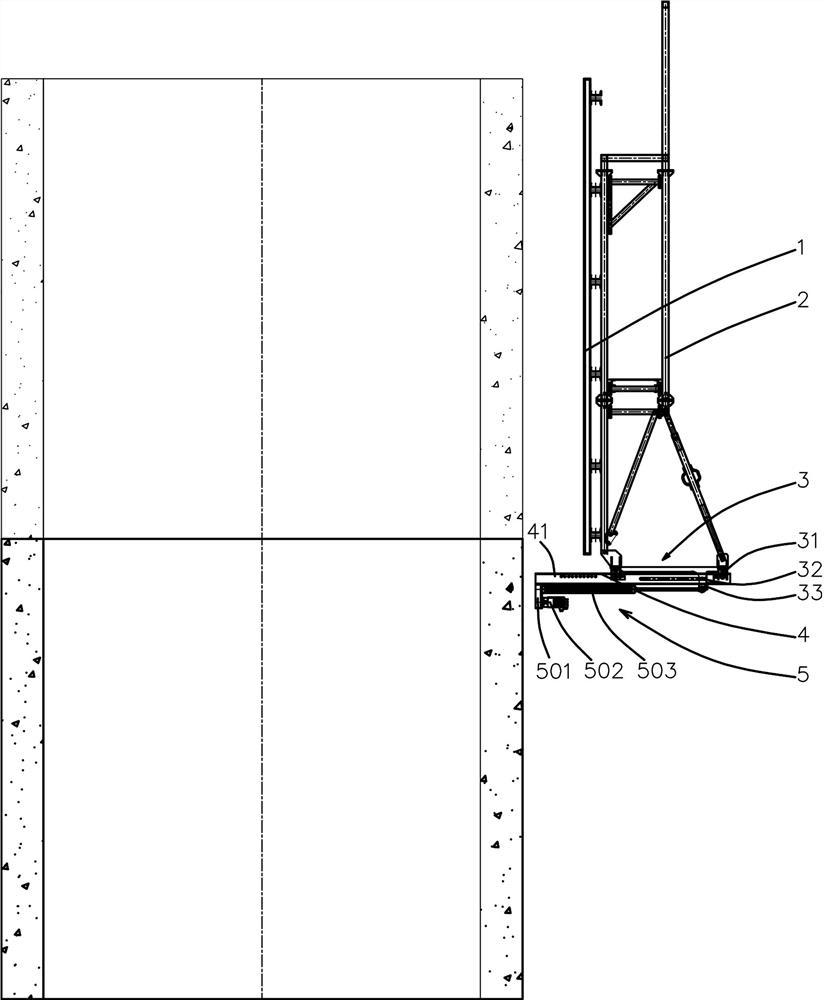
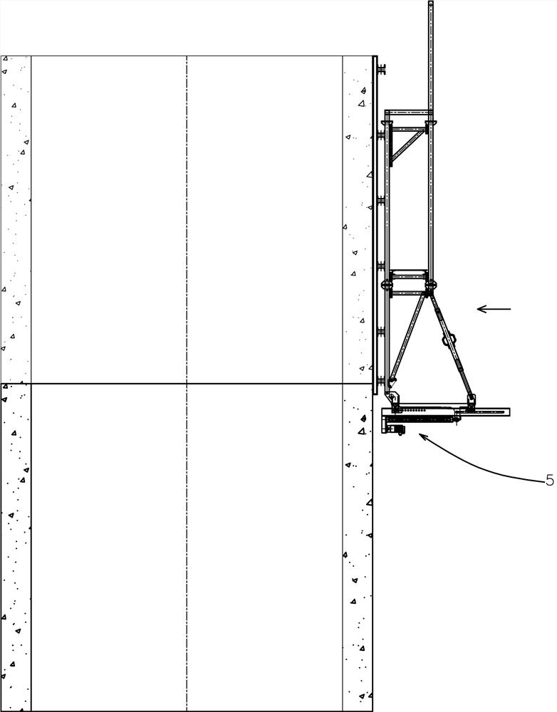
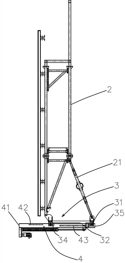
[0058] like Figures 1~3 Among them, an automatic vertical mold ejection drive device for a template, comprising an ejection platform 3 and a sliding platform 4, the ejection platform 3 is used to connect with the template support system 2, and the ejection platform 3 is slidably connected with the sliding platform 4;

[0059] Between the ejection platform 3 and the sliding platform 4, there is a die ejection drive mechanism 5, and the structure of the ejection ejection drive mechanism 5 is as follows: one end of the retractable screw nut mechanism 503 is connected to the ejection platform 3, and the other end is connected to the sliding platform 3. The platform 4 is connected, and the screw nut mechanism 503 is connected with the drive motor 502 . When in use, the ejection platform 3 is fixedly connected with the formwork support system 2, and is usually located at the bottom of the formwork support system 2. There is a formwork 1 on the formwork support system 2, and the sli...

Embodiment 2

[0075] On the basis of Example 1, as Figure 8 In the above, an intelligent control method for the above-mentioned automatic vertical mold ejection drive device of the template, comprising the following steps:

[0076] S1. There are multiple drive motors 502. Usually, there are multiple formwork support systems 2 at each construction location, and multiple formwork support systems 2 are provided at the bottom of the formwork support system 2 with a plurality of ejector drive mechanisms 5. In the cluster control structure, the difficulty of control is to ensure the synchronization of multiple die-removing driving mechanisms 5, and the cost cannot be unacceptable. The PLC controls each drive motor 502 to stretch out until the zero position sensor 506 is triggered, so that the screw rod 504 is at the zero position. With this structure, each drive motor 502 is reset to zero, and a higher control accuracy is obtained. With this structure, for the entire system The installation acc...

Embodiment 3

[0086] On the basis of embodiment 1 or 2, as Figure 8 In the above, an intelligent control method for the above-mentioned automatic vertical mold ejection drive device of the template, comprising the following steps:

[0087] S7, read the stroke parameters of the locking motor 351, and convert the stroke parameters into preset angle parameters;

[0088] S8. The PLC controls the action of the locking motor 351, and the locking angle sensor 357 feeds back the angle parameters. The angle parameters should be consistent with the input control parameters of the locking motor 351. If they are different, an alarm will be issued;

[0089] If the preset rotation angle parameter is reached, the locking motor 351 stops;

[0090] S9, read the travel parameters of the driving motor 502, and convert the travel parameters into preset angle parameters;

[0091] Read the torque parameters of the drive motor 502, that is, the maximum and minimum output torque ranges of the drive motor 502, a...


PUM


Abstract

The invention provides an automatic formwork erecting and withdrawing driving device and an intelligent control method.The automatic formwork erecting and withdrawing driving device comprises a withdrawing platform and a sliding platform, the withdrawing platform is used for being connected with a formwork support system, and the withdrawing platform is slidably connected with the sliding platform; a mold withdrawing and erecting driving mechanism is arranged between the mold withdrawing platform and the sliding platform, and adopts the structure that one end of a telescopic lead screw nut mechanism is connected with the mold withdrawing platform, the other end of the telescopic lead screw nut mechanism is connected with the sliding platform, and the lead screw nut mechanism is connected with a driving motor. By adopting an electric driving mode and matching with the structures of the sliding rails and the rollers, high-precision mold erecting can be realized, and automatic and intelligent control can be more conveniently realized by adopting the electric driving mode. The structure of the cantilever limiting wheel is adopted, the sliding rail can be hooked reversely, the formwork is prevented from turning over, and the construction safety is improved through the cooperation of the structure of the limiting sliding groove and the sliding limiting pin. A preferable lead screw nut mechanism is adopted, an independent guide structure is omitted, and the thrust of the lead screw nut mechanism is larger under the same weight.

Description

technical field [0001] The invention relates to the field of bridge construction equipment and methods, in particular to a driving device for automatic vertical form removal of a formwork and an intelligent control method. Background technique [0002] The construction of existing large-scale concrete components, such as the construction of concrete structures such as piers, towers, etc., mostly adopts formwork support structures, such as automatic climbing formwork construction, to realize the overall vertical formwork and demoulding of large formwork to improve construction efficiency. The existing large-scale formwork adopts manual operation for vertical formwork and demoulding. The formwork construction process of piers, towers and other structures is mostly at high altitude, and the self-weight of large formwork is heavier, the labor of construction personnel is strong, and the construction risk is also high. In the prior art, there is also a scheme of using a formwork...

Claims


Application Information

Patent Timeline
Patent Type & Authority Applications(China)
IPC IPC(8): E01D21/00
CPCE01D21/00
Inventor 张超李拔周李阳田涛余汉锦林治民吴柯汪华文狄飞超王磊罗平王炜
Owner CCCC WUHAN HARBOR ENG DESIGN & RES
Why Eureka
Try Eureka