
Explosion field shock wave power capability and heat effect coupling measurement device and method

A technology of coupling measurement and shock wave, which is applied in measurement devices, material explosiveness, nuclear power generation, etc., can solve the problems of insufficient test accuracy and susceptibility to electromagnetic interference, and achieve the effects of high sensitivity, improved measurement accuracy, and high measurement accuracy.

Pending Publication Date: 2022-07-08
NAT UNIV OF DEFENSE TECH
View PDF0 Cites 0 Cited by
  • Summary
  • Abstract
  • Description
  • Claims
  • Application Information

AI Technical Summary

Problems solved by technology

[0021] The technical problem to be solved by the present invention is to provide a device and a measurement method capable of simultaneously measuring the working capacity of the pressure field and the thermal dose of the temperature field. Simple structure, low cost, reusable core components, strong anti-electromagnetic interference ability, convenient post-processing of results, can be used for rapid measurement of pressure field and temperature field under different geographical conditions, ability to work for pressure field, rapid thermal dose of temperature field Quantitative measurement provides a new reference option; the measurement device can realize the coupling measurement of the shock wave work and thermal effect of the explosion field, and solve the shortcomings of the existing measurement methods such as susceptibility to electromagnetic interference and insufficient test accuracy

Method used


Image

  • Explosion field shock wave power capability and heat effect coupling measurement device and method
  • Explosion field shock wave power capability and heat effect coupling measurement device and method
  • Explosion field shock wave power capability and heat effect coupling measurement device and method

Examples


Embodiment Construction

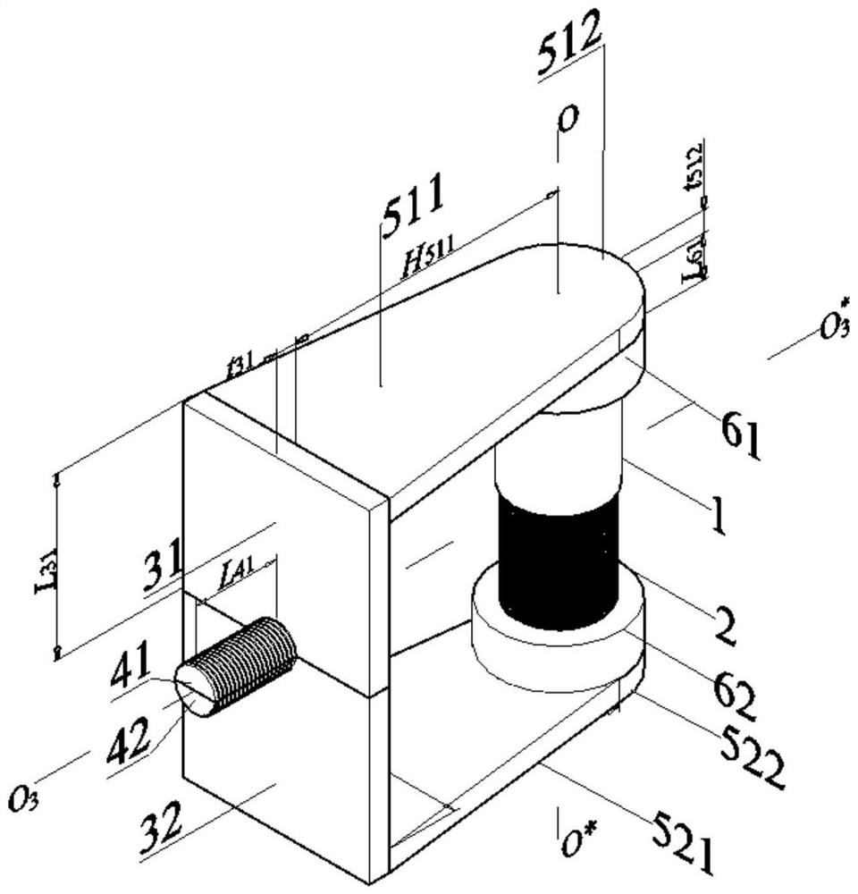
[0059] like figure 1 As shown, the measuring device of the present invention consists of a thin-walled metal tube (1), a shape memory alloy spring (2), a base (3), a bolt (4), a support plate (5), and two sleeves (6). The shape memory alloy spring (2) is prepared from a single-pass shape memory alloy, and is placed inside the thin-walled metal tube (1) along the axis OO* direction of the thin-walled metal tube (1). coaxial.

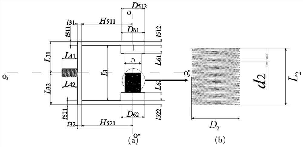
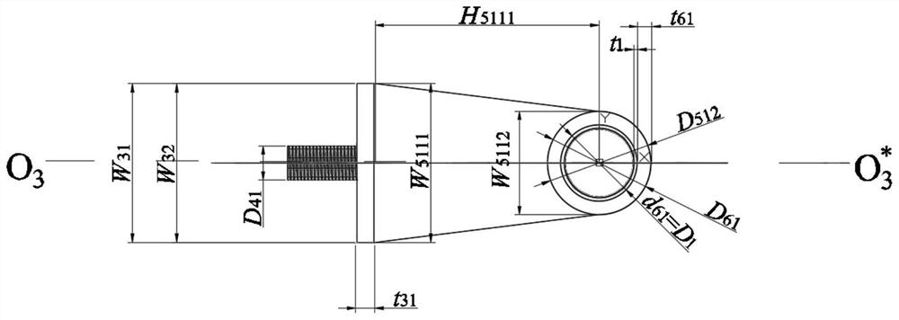
[0060] like figure 2 As shown in (a), the thin-walled metal tube (1) is cylindrical in shape and has no end faces. It is used to load the shape memory alloy spring 2 and convert the work performance of the shock wave pressure field into the deformation of the metal tube, which can be changed by changing the thickness of the side wall. t 1 Adjust the temperature measurement sensitivity. like Figure 4 As shown, the outer diameter of the thin-walled metal tube (1) is D 1 Satisfy 5mm≤D 1 ≤50mm, wall thickness t 1 Satisfy 0.5mm≤t 1 ≤5mm, inner diame...


PUM

PropertyMeasurementUnit
Diameteraaaaaaaaaa
Thicknessaaaaaaaaaa
Yield strengthaaaaaaaaaa

Abstract

The invention discloses a coupling measurement device and method for shock wave acting capacity and heat effect of an explosion field, and aims to realize coupling measurement of shock wave acting capacity and heat effect of the explosion field. The measuring device is composed of a thin-wall metal tube, a one-way shape memory alloy spring, a base, a supporting plate and two sleeves, and the thin-wall metal tube and the one-way shape memory alloy spring are core sensing elements. The shock wave acting capacity is quantitatively converted into thin-walled tube deformation by using the compression deformation characteristic of the thin-walled metal tube, and the thermal dose parameter in the thermal effect is quantitatively converted into spring deformation by using the thermal deformation characteristic of the shape memory alloy spring, so that the shock wave acting and thermal effect coupling rapid quantitative measurement of the explosion field is realized. The one-way shape memory alloy spring is stable in structure after being heated and deformed and can be repeatedly used. The device is simple in structure, free of power supply, convenient to arrange and use, low in use cost, capable of being repeatedly used, simple in measurement method, free of electromagnetic interference and accurate.

Description

technical field [0001] The invention belongs to the fields of energy detection and thermal detection, and relates to an integrated device for energy measurement and heat measurement of an object target in an explosion shock wave pressure field and temperature field, and more particularly, to a device utilizing shape memory alloy and thin-walled metal tube A measuring device and method for simultaneously detecting the shock wave work and transient temperature field thermal effects generated by an object target in an explosion. Background technique [0002] When the explosive explodes in the air, high-temperature, high-pressure, and high-speed explosive products are instantly produced, which in turn violently compress the adjacent air medium, causing its pressure, density and temperature to increase stepwise, forming an air shock wave and propagating outward. . Air shock wave is one of the main factors for the damage and destruction of personnel, equipment and protective stru...

Claims


Application Information

Patent Timeline
IPC IPC(8): G01N3/313G01N25/54
CPCG01N3/313G01N25/54G01N2203/0682Y02E30/30
Inventor 林玉亮韩国振祁子真张玉武陈荣李志斌梁民族李翔宇卢芳云
Owner NAT UNIV OF DEFENSE TECH
Learn More