Heat conduction structural member, heat conduction shell and heater
A technology of heat conduction structure and structural parts, which is applied in the direction of ohmic resistance heating parts, etc., can solve the problems of low heat conduction performance and high cost, and achieve the effects of improving heat conduction performance, facilitating heat conduction, and reducing costs
- Summary
- Abstract
- Description
- Claims
- Application Information
AI Technical Summary
Problems solved by technology
Method used
Image
Examples
Embodiment 1
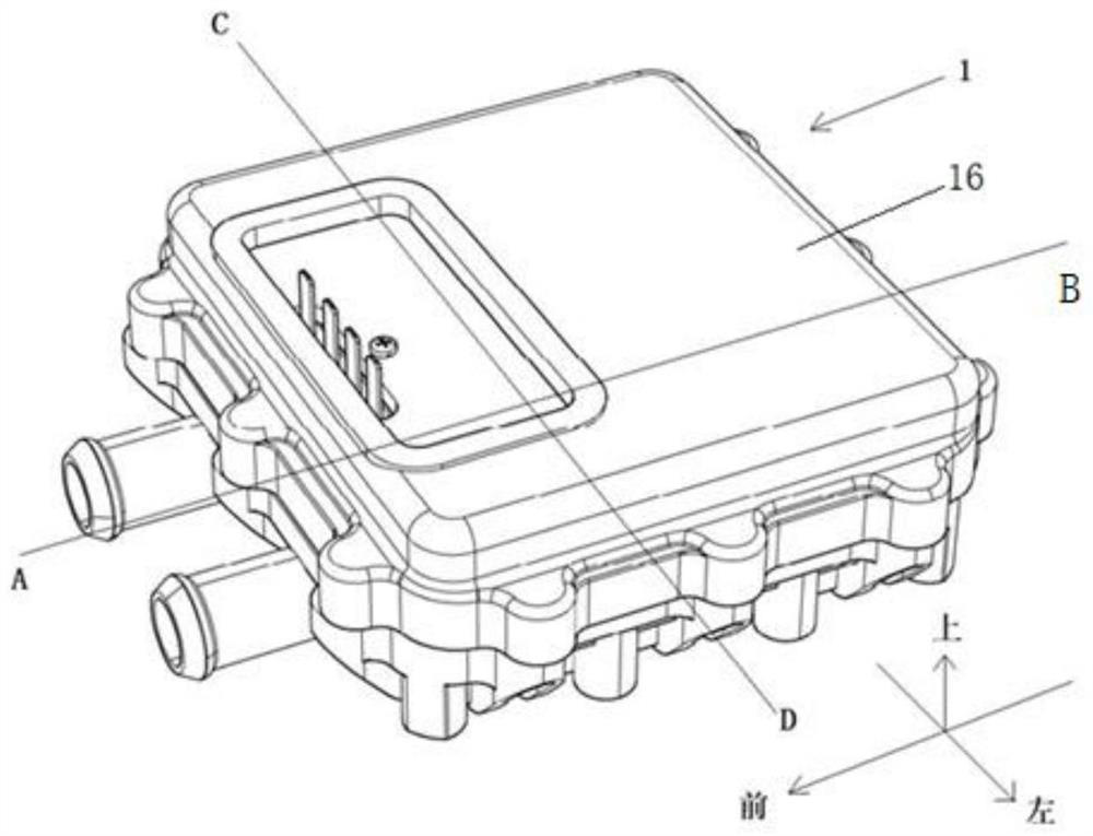
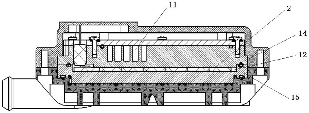
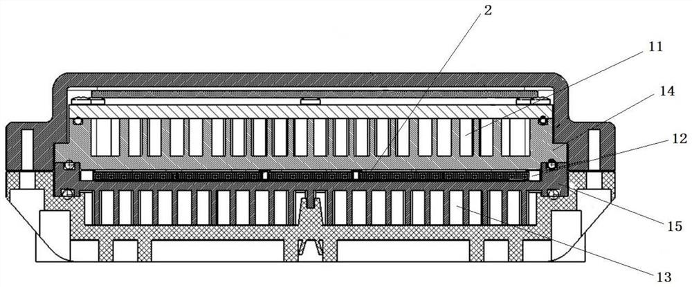
[0107] like Figure 5 and Image 6 As shown, this embodiment provides a PTC heater, which includes a heating box body 1 and a PTC thermistor element 2 . The heating box body 1 includes a polymer material shell 16 and a heat-conducting shell body. The heat-conducting shell body is disposed in the polymer material shell 16 , so that the heating box 1 forms a first heat dissipation cavity 11 , a heat generation cavity 12 and a second heat dissipation cavity 13 from top to bottom. The heat-generating cavity 12 is surrounded by a first heat-conducting casing 14 and a second heat-conducting casing 15, and is a sealed cavity. The first heat-conducting shell 14 and the second heat-conducting shell 15 are collectively called a heat-conducting shell body, and the heat-generating cavity 12 is a cavity enclosed by the aforementioned heat-conducting shell body. The heat-generating cavity 12 and the first heat-dissipating cavity 11 are separated by a first heat-conducting casing 14 . Th...
Embodiment 2
[0123] The main difference between this embodiment and Embodiment 1 is:
[0124] A thermally conductive phase change material is filled between the PTC thermistor element 2 and the shell of the heat-generating cavity 12 to replace the liquid-phase thermally conductive material 4. The thermally conductive phase-change material is solid when filled into the heat-generating cavity 12, and is When the PTC thermistor element 2 is heated to a predetermined temperature during operation, the thermally conductive phase change material changes into a liquid state and fills the heat generating cavity 12 .
[0125]In this way, the thermally conductive phase change material is used as the filling material, and when the PTC thermistor element 2 is heated to a predetermined temperature, the thermally conductive phase change material is converted into a liquid state, which can fully conduct heat, and at the same time, there is no need to connect the PTC thermistor element 2 to the thermal cond...
Embodiment 3
[0129] like Figure 7 to Figure 9 As shown, the main difference between this embodiment and Embodiment 1 is:
[0130] The surfaces of the positive electrode sheet 21 and the negative electrode sheet 22 are not provided with the first insulating and thermally conductive coating 31 . The inner wall of the heat-generating cavity 12 , that is, the inner wall of the first thermally conductive casing 14 and the inner wall of the second thermally conductive casing 15 are both coated with a second insulating and thermally conductive coating 32 . The second insulating and thermally conductive coating 32 is an alumina coating, which is sprayed on the inner walls of the first thermally conductive casing 14 and the second thermally conductive casing 15 by thermal spraying. The thickness of the second insulating and thermally conductive coating 32 is 0.08 mm, and the insulation resistance of the second insulating and thermally conductive coating 32 is 2 Mohm. A liquid-phase thermally con...
PUM
 Abstract
Description
Claims
Application Information
 - R&D
- Intellectual Property
- Life Sciences
- Materials
- Tech Scout
- Unparalleled Data Quality
- Higher Quality Content
- 60% Fewer Hallucinations
Browse by: Latest US Patents, China's latest patents, Technical Efficacy Thesaurus, Application Domain, Technology Topic, Popular Technical Reports.
© 2025 PatSnap. All rights reserved.Legal|Privacy policy|Modern Slavery Act Transparency Statement|Sitemap|About US| Contact US: help@patsnap.com


