
Atomizer and related method of operation

An atomizer and rotary atomizer technology, applied in the field of atomizers, can solve the problems of cycle time loss, time prolongation of the coating system cycle time, impossible to clean the atomizer at the same time, etc., to eliminate cleaning and maintenance, The effect of omitting exhaust gas purification and saving costs

Pending Publication Date: 2022-07-08
DUERR SYST GMBH
View PDF3 Cites 0 Cited by
  • Summary
  • Abstract
  • Description
  • Claims
  • Application Information

AI Technical Summary

Problems solved by technology

However, this requires the rotary atomizer to move to the collection hopper, which takes additional time and results in a substantial loss of cycle time, i.e. the time required to change paint extends the cycle time required for the painting system
[0008] Another disadvantage of this flushing of multi-component paint into a collection hopper or container is that it is not possible to simultaneously clean the outer surfaces of the atomizer during a paint change
Therefore, these process steps have to be performed one after the other, which in turn requires additional time

Method used

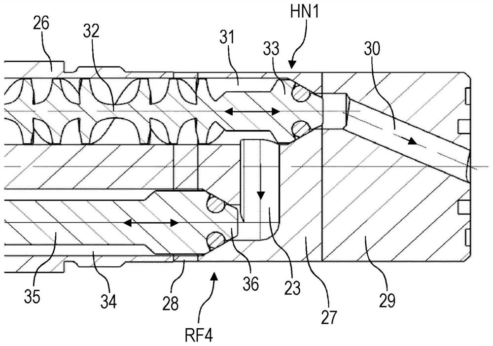
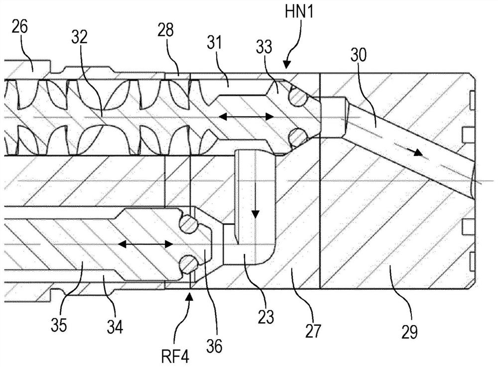

Image

  • Atomizer and related method of operation
  • Atomizer and related method of operation
  • Atomizer and related method of operation

Examples


Embodiment Construction

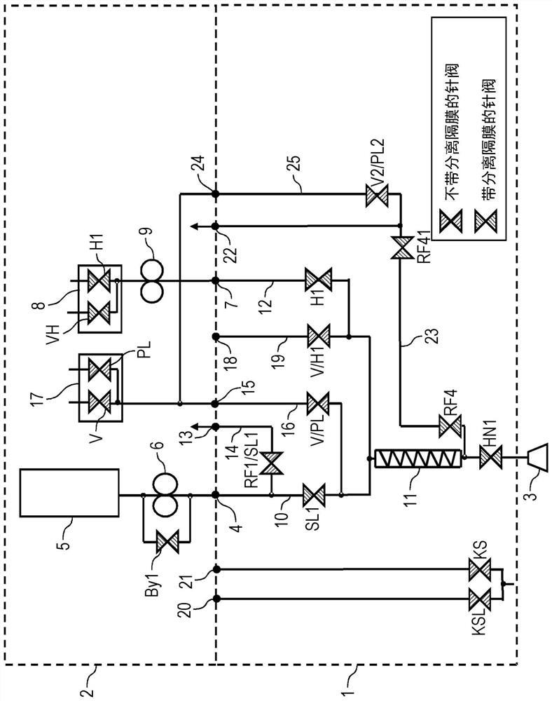
[0069] figure 1 A schematic diagram of a rotary atomizer 1 according to the present invention is shown, which is mounted on the robotic arm 2 of a conventional painting robot with a serial robotic kinematic mechanism. The robotic arm 2 is the distal robotic arm of the painting robot, which is also referred to as "arm 2" in common technical terms.

[0070] As is known from the prior art, the rotary atomizer 1 is used to apply multi-component coatings via a rotating bell cup 3 .

[0071] In order to supply the main paint, the rotary atomizer 1 has a main paint connection 4 which is supplied with the required main paint through a color changer 5 in the robot arm 2 .

[0072] A metering pump 6 is arranged between the color changer 5 and the main paint connection 4 of the rotary atomizer 1 to deliver the main paint in the desired paint flow. The metering pump 6 can be bypassed by a bypass valve By1 connected in parallel.

[0073] Furthermore, the rotary atomizer 1 has a hardener...


PUM


Abstract

The invention relates to an atomizer (1) for applying a multi-component coating, comprising a main coating connection (4), a hardener connection (7), a mixer (11), a hardener line (12) in the atomizer (1) leading from the hardener connection (7) to the mixer (11), a main coating line (10) in the atomizer (1) leading from the main coating connection (4) to the mixer (11), and a main valve (HN1) for controlling the delivery of the coating, a main valve (HN1) is arranged downstream of the mixer (11) and controls the flow of the multi-component coating to the coating element (3), more particularly to the rotatable bell cup (3). The atomizer (1) according to the invention is characterized by a first return connection (22) for returning the multi-component coating from the atomizer (1) to the return system. For this purpose, the atomizer (1) has a first return line (23) which branches in the atomizer (1) between the mixer (11) and the main valve (HN1) and opens into the first return connection (22). The invention further relates to a corresponding operating method.

Description

technical field [0001] The present invention relates to an atomizer (eg, a rotary atomizer) for applying multi-component coatings and an associated method of operation. Background technique [0002] In modern paint plants for painting motor vehicle body parts, rotary atomizers are often used as coating devices, which in one design can also apply multi-component coatings, which are sprayed in the rotary atomizer. Composed of main paint and hardener mixed together. Such a coating system is known, for example, from patent document DE 10 2015 010 158 A1. [0003] The problem here is the build-up of paint residues that occurs, for example, in the process of changing the color. [0004] A possible solution for this is to use a so-called wet cleaning system. In this case, the multi-component reactive coating material introduced into the wet wash is filtered out of the water with suitable chemicals (e.g. flocculants, flotation agents), and the filtrate must then be disposed of as...

Claims


Application Information

Patent Timeline
Patent Type & Authority Applications(China)
IPC IPC(8): B05B1/30
CPCB05B3/1014B05B7/0408B05B15/55B05B1/3093B05B15/58B05B1/3046B01F25/43141B05B14/00B01F2101/30
Inventor B·塞茨S·赫尔曼E·弗吕佐尔格
Owner DUERR SYST GMBH
Learn More