
Neodymium-iron-boron product cutting equipment

A cutting equipment, NdFeB technology, applied in the direction of shearing machine equipment, metal processing equipment, shearing devices, etc., can solve the problems of inability to reuse magnet waste and cutting fluid, increased work intensity, and reduced cutting efficiency. Achieve the effect of reducing the cumbersome feeding, avoiding accidental injury, reducing shaking and tilting

Inactive Publication Date: 2022-07-12
徐州永丰磁业有限公司
View PDF0 Cites 0 Cited by
  • Summary
  • Abstract
  • Description
  • Claims
  • Application Information

AI Technical Summary

Problems solved by technology

[0003] In order to solve the above technical problems, a cutting equipment for NdFeB products is provided. This technical solution solves the problem that in the cutting process of the existing cylindrical NdFeB products proposed in the above background technology, it is usually manually loaded and fixed. , positioning, it is impossible to automatically load, fix, and position, resulting in increased work intensity, and not only is it easy to generate a large amount of magnet waste during the cutting process, but it is also impossible to automatically collect the magnet waste and cutting fluid for secondary use, resulting in The cut magnet waste is easy to accumulate on the equipment, resulting in the problem of reduced cutting efficiency and easy damage to the equipment, and the problem that the cut magnet waste and cutting fluid cannot be reused

Method used


Image

  • Neodymium-iron-boron product cutting equipment
  • Neodymium-iron-boron product cutting equipment
  • Neodymium-iron-boron product cutting equipment

Examples


Embodiment 1

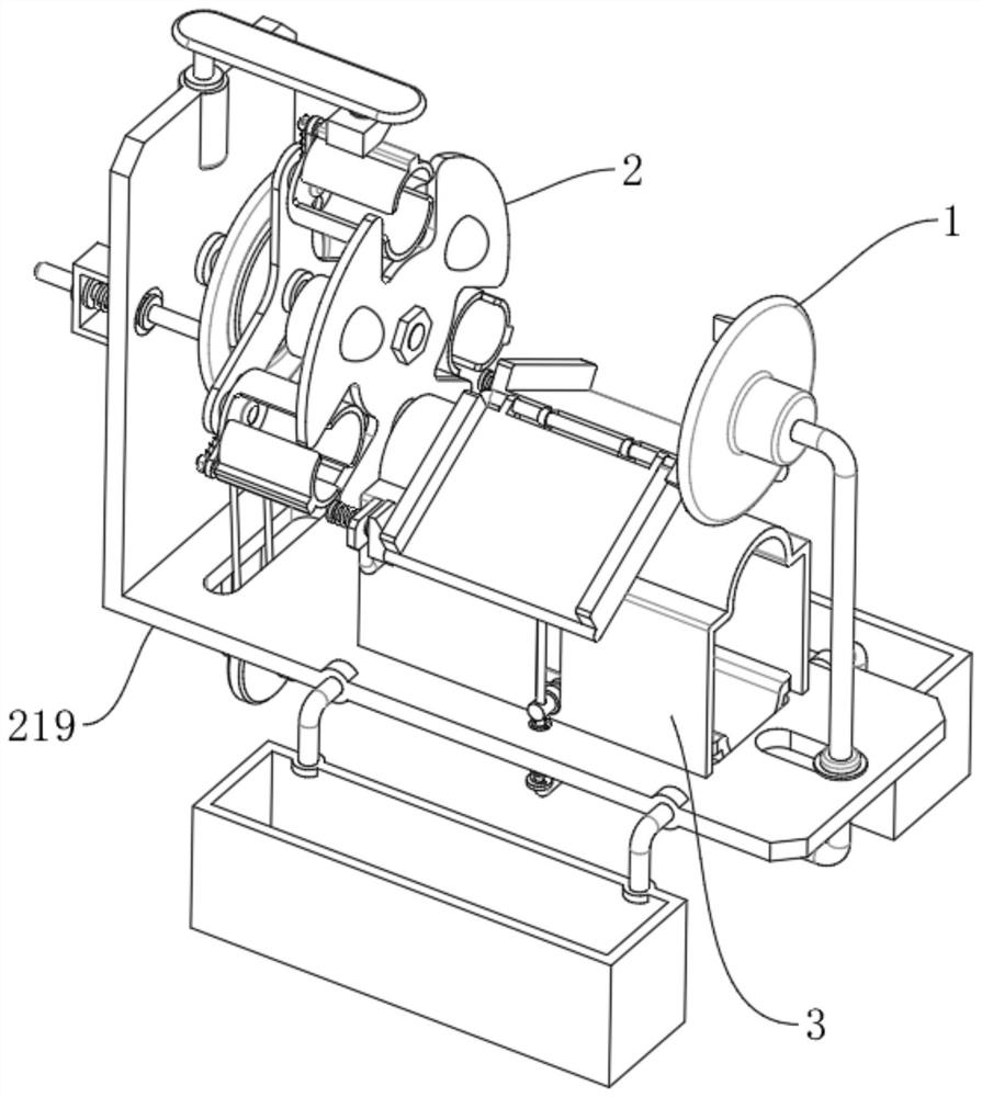
[0031] Please refer to Figure 1 to Figure 7As shown, a NdFeB product cutting equipment includes a cutting machine body 1, the left end of the cutting machine body 1 is provided with an automatic clamping and fixing replacement mechanism 2, and the right end of the automatic clamping and fixing replacement mechanism 2 is provided with an automatic feeding mechanism 3 , the automatic clamping and fixing replacement mechanism 2 includes a shaft 201, a triangular plate 202, a semi-cylinder 203, a short slot 204, a semi-circular upper cover 205, a power spring rod 206, an electromagnet 207, and a bending plate 219. The left end of the shaft 201 is rotatably connected with a Bending plate 219, a triangular plate 202 is fixedly connected to the right end of the shaft rod 201, one end of the triangular plate 202 is fixedly connected with a plurality of semi-cylinders 203, one end of the semi-cylinder 203 is provided with a short groove 204, and one end of the short groove 204 is slida...

Embodiment 2

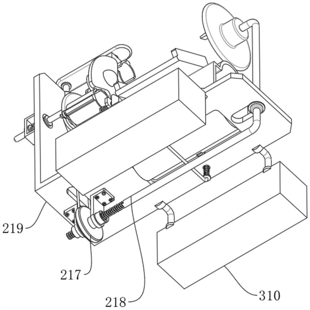
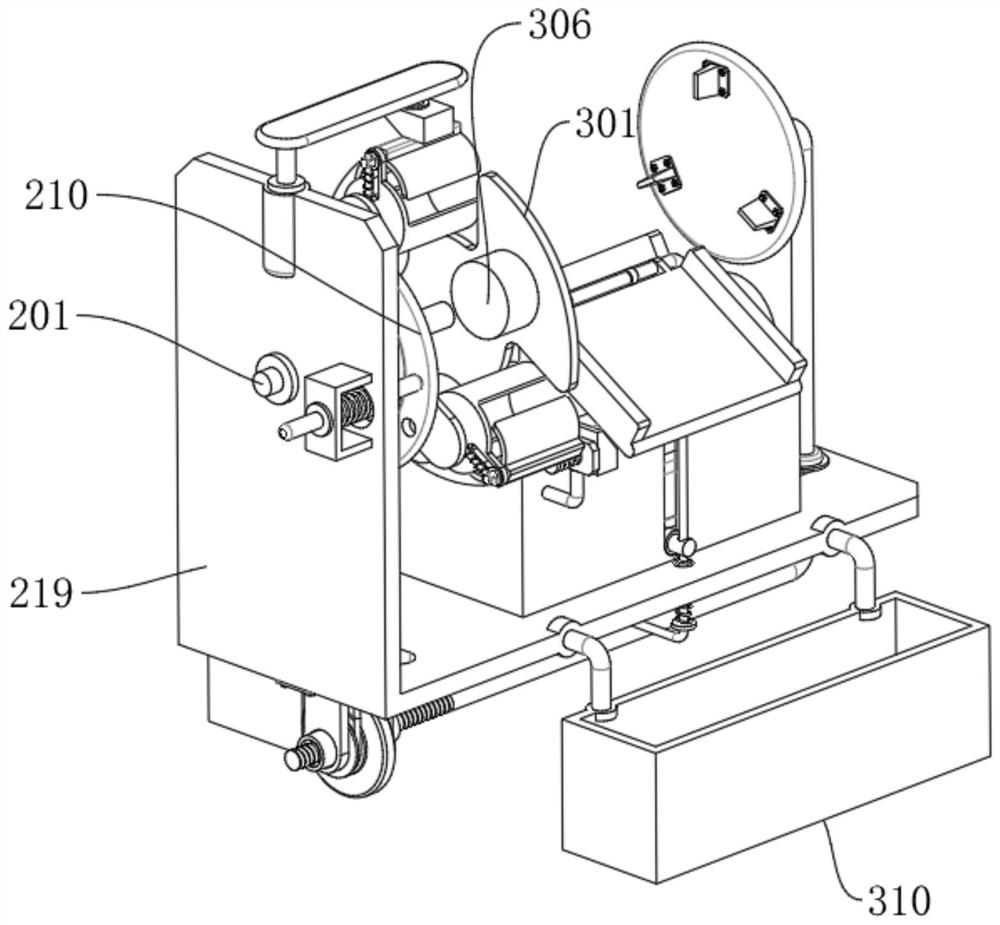
[0034] Please refer to Figure 5 and Figure 7 and Figure 8 As shown, the automatic feeding mechanism 3 includes a gap blocking plate 301, a storage bin 302, a semicircular feeding plate 303, and a curved spring rod 304. The right end of the shaft rod 201 is fixedly connected with a gap blocking plate 301, and the right end of the gap blocking plate 301 is provided There is a storage bin 302, the lower end of the storage bin 302 is fixedly connected to the upper end surface of the bending plate 219, the lower end of the storage bin 302 is slidably connected with a semicircular feeding plate 303, and the left and right ends of the semicircular feeding plate 303 are slidably connected with curved spring rods 304 , the lower end of the bending spring rod 304 is fixedly connected to the lower end of the bending plate 219, a plurality of balls 305 are evenly slidably connected to the gap blocking plate 301, and each ball 305 abuts a spring cylinder 306, and these spring cylinders...

Embodiment 3

[0038] Please refer to Figure 1 to Figure 8 As shown, a NdFeB product cutting equipment includes a cutting machine body 1, the left end of the cutting machine body 1 is provided with an automatic clamping and fixing replacement mechanism 2, and the right end of the automatic clamping and fixing replacement mechanism 2 is provided with an automatic feeding mechanism 3. The clamping and fixing replacement mechanism 2 includes a shaft rod 201, a triangular plate 202, a semi-cylinder 203, a short groove 204, a semi-circular upper cover 205, a power spring rod 206, an electromagnet 207, and a bending plate 219. The left end of the shaft rod 201 is rotatably connected with a bending The plate 219, the right end of the shaft 201 is fixedly connected with a triangular plate 202, one end of the triangular plate 202 is fixedly connected with a plurality of semi-cylinders 203, one end of the semi-cylindrical 203 is provided with a short groove 204, and one end of the short groove 204 is ...


PUM


Abstract

The neodymium iron boron product cutting equipment comprises a cutting machine body, an automatic clamping, fixing and replacing mechanism is arranged at the left end of the cutting machine body, an automatic feeding mechanism is arranged at the right end of the automatic clamping, fixing and replacing mechanism, the automatic clamping, fixing and replacing mechanism comprises a shaft rod, and the left end of the shaft rod is rotationally connected with a bending plate; after a cylindrical neodymium iron boron product needing to be cut is stored in the storage bin, the motor arranged at one end of the shaft rod drives the shaft rod to rotate, and the shaft rod drives the triangular plate to rotate; the triangular plate drives the semicircular cylinders connected with the three end points of the triangular plate to rotate and replace, when one end of the triangular plate moves to the discharging port of the storage bin, the electrified magnets arranged in the semicircular cylinders are powered through the wireless induction electrifying devices arranged in the bent plates, and at the moment, the electrified magnets generate magnetic force; and the cylindrical neodymium iron boron product in the storage bin is sucked into the semicircular cylinder.

Description

technical field [0001] The invention relates to the field of NdFeB products, in particular to NdFeB product cutting equipment. Background technique [0002] During the cutting process of the existing cylindrical NdFeB products, the loading, fixing and positioning are usually performed manually, and the loading, fixing and positioning cannot be carried out automatically, which leads to an increase in the work intensity, and is not only easy to produce during the cutting process. A large amount of magnet waste chips, and the magnet waste chips and cutting fluid cannot be automatically collected for secondary use, which leads to the easy accumulation of magnet waste chips on the equipment, resulting in reduced cutting efficiency and equipment damage. Use the magnet waste chips and cutting fluids that have been cut. SUMMARY OF THE INVENTION [0003] In order to solve the above-mentioned technical problems, a NdFeB product cutting equipment is provided. This technical solution...

Claims


Application Information

Patent Timeline
Patent Type & Authority Applications(China)
IPC IPC(8): B23D19/00B21D43/28B23Q7/00B23Q7/04B23Q7/10B23Q11/00B23Q11/10
CPCB23D19/00B21D43/28B23Q7/00B23Q7/04B23Q7/10B23Q11/0042B23Q11/0067B23Q11/10Y02P70/10
Inventor 张昌州
Owner 徐州永丰磁业有限公司
Learn More