

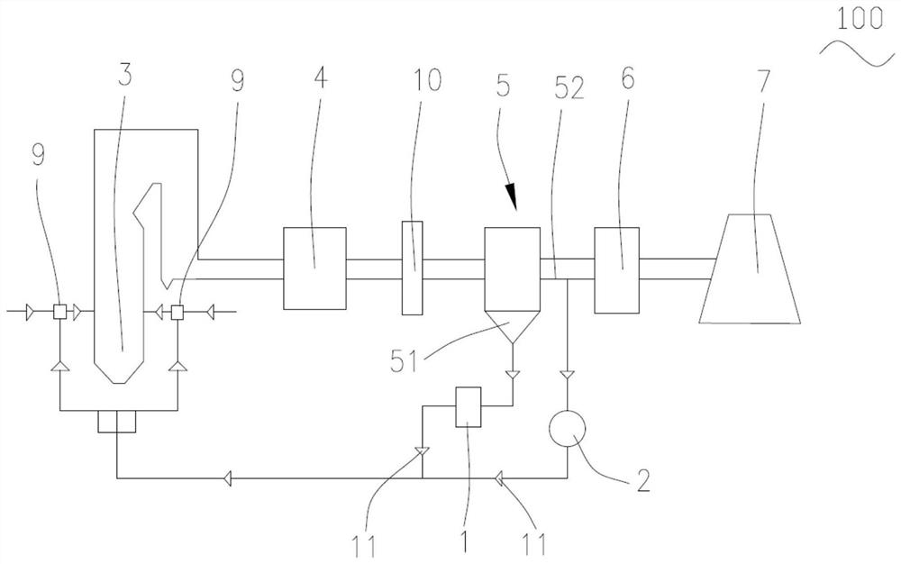
Combustion system with flue gas and fly ash circulation function
A technology of circulation function and combustion system, applied in combustion equipment, climate sustainability, climate change adaptation, etc., can solve the problems of CO concentration and carbon content in fly ash, high temperature corrosion of water wall, etc., to prevent slagging Contamination, avoid wear, reduce the effect of corrosion damage
- Summary
- Abstract
- Description
- Claims
- Application Information
AI Technical Summary
Problems solved by technology
Method used
Image

Examples
Embodiment Construction
[0024] The technical solutions in the embodiments of the present invention will be clearly and completely described below with reference to the accompanying drawings in the embodiments of the present invention. Obviously, the described embodiments are only a part of the embodiments of the present invention, rather than all the embodiments. Based on the embodiments of the present invention, all other embodiments obtained by those of ordinary skill in the art without creative efforts shall fall within the protection scope of the present invention.
[0025] In the description of the present invention, it should be noted that the terms "center", "portrait", "horizontal", "top", "bottom", "front", "rear", "left", "right", " The orientation or positional relationship indicated by vertical, horizontal, top, bottom, inner, outer, etc. is based on the orientation or positional relationship shown in the drawings, and is only for the convenience of describing the present invention and Th...
PUM
 Abstract
Description
Claims
Application Information