Pattern reconfigurable antenna based on PIN tube

A technology for reconstructing antennas and directional patterns, applied in the directions of antennas, antenna grounding devices, radiating element structures, etc., can solve the problems of high profile and large antenna volume, etc., and achieve the effect of low profile and small size

Active Publication Date: 2022-07-12
SOUTH CHINA UNIV OF TECH
View PDF5 Cites 1 Cited by
  • Summary
  • Abstract
  • Description
  • Claims
  • Application Information

AI Technical Summary

Problems solved by technology

[0004] Most of the existing pattern reconfigurable antennas use larger reflectors, making the antenna larger in size and higher in profile

Method used


Image

  • Pattern reconfigurable antenna based on PIN tube
  • Pattern reconfigurable antenna based on PIN tube
  • Pattern reconfigurable antenna based on PIN tube

Examples


Embodiment

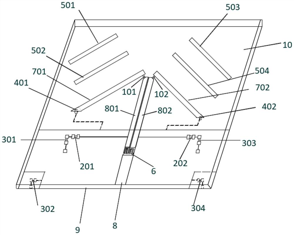
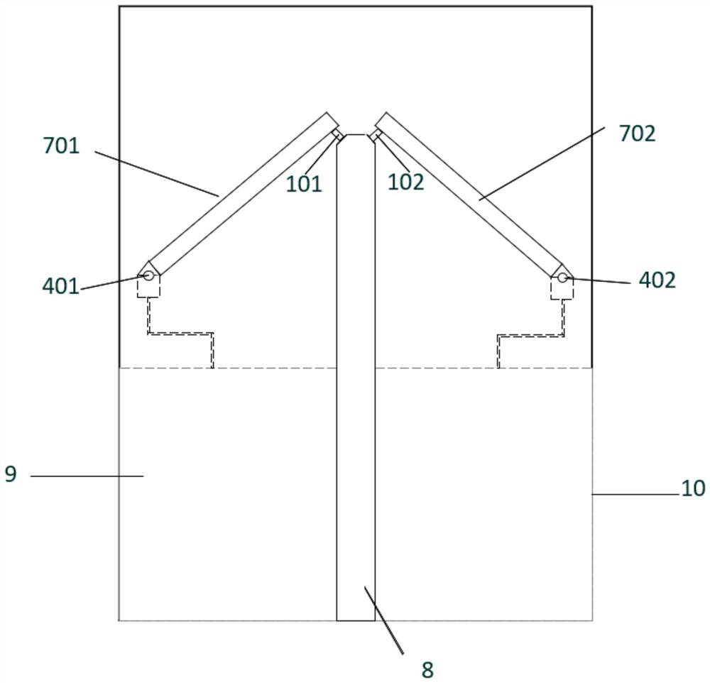
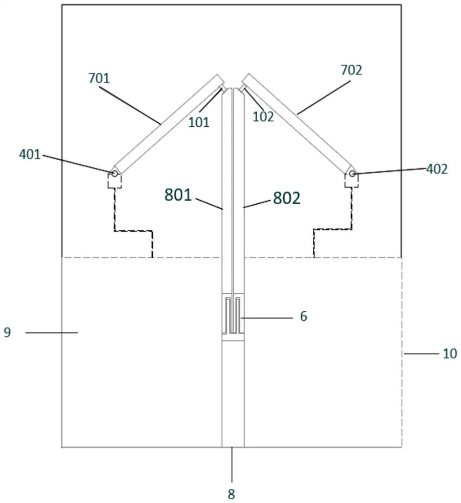
[0062] A pattern reconfigurable antenna based on PIN tube, such as figure 1 , figure 2 , image 3 and Figure 4 As shown, it includes an antenna radiation unit, a dielectric substrate 10, a metal floor 9, a parasitic unit, a first PIN tube 101, a second PIN tube 102, a first PIN tube bias circuit and a second PIN tube bias circuit;

[0063] The antenna radiation unit includes a microstrip line 8, a first metal sheet 701 and a second metal sheet 702;

[0064] The microstrip line, the first metal sheet 701, the second metal sheet 702, the parasitic unit, the first PIN tube 101 and the second PIN tube 102 are located on the upper surface of the dielectric substrate;

[0065] The metal floor is located on the lower surface of the dielectric substrate;

[0066] The microstrip line is located in the center of the upper surface of the dielectric substrate, and two sides of one end of the microstrip line are respectively connected to one end of the first PIN tube 101 and one end ...

Embodiment 2

[0099] In this embodiment, Figure 8 , Figure 9 , Figure 10 It is the simulated performance when the antenna is in the third mode 3 working state. Figure 8 is the S11 parameter, and it can be seen from the figure that the impedance bandwidth of the antenna in the third mode 3 working state is 3.27 GHz to 3.67 GHz, and the relative bandwidth is 11.5%. Figure 9 Given the radiation pattern when the antenna is in the third mode 3 working state at 3.5GHz, Figure 10 Given the change of gain with frequency in the maximum radiation direction, it can be seen from the figure that the maximum radiation direction of the antenna at 3.5GHz when the antenna is in the third mode 3 working state points to 50° of the xoy plane, and the gain is 6.42dBi.

Embodiment 3

[0101] In this embodiment, Figure 11 , Figure 12 and Figure 13 It is the simulated performance when the antenna is in the second mode 2 working state. Figure 11 is the S11 parameter, and it can be seen from the figure that the impedance bandwidth of the antenna in the second mode 2 working state is 3.26 GHz to 3.66 GHz, and the relative bandwidth is 11.5%. Figure 12 Given the radiation pattern when the antenna is in the second mode 2 working state at 3.5GHz, Figure 13 Given the change of gain with frequency in the maximum radiation direction, because the antenna is in the second mode 2 working state, it is a two-way radiation mode, that is, there are two maximum lobes in the pattern, so the maximum radiation direction of the pattern at 3.5GHz points to are -50° and 50° of the xoy plane, and the gains are 4.57dBi and 4.45dBi, respectively.


PUM


Abstract

The invention discloses a directional diagram reconfigurable antenna based on a PIN tube. The antenna comprises an antenna radiation unit, a dielectric substrate, a metal floor, a parasitic unit, a first PIN tube, a second PIN tube, a first PIN tube bias circuit and a second PIN tube bias circuit. The antenna radiation unit comprises a microstrip line, a first metal sheet and a second metal sheet. According to the antenna, a large reflecting plate is not needed, the PIN tube is used as a reconfigurable device, and a directional diagram reconfigurable antenna which is low in profile, small in size and capable of working at 3.5 GHz is achieved. An interdigital capacitor is added in a radiation structure, and a fine gap is formed upwards along the center of the interdigital capacitor and extends to the top of a microstrip line, so that the two PIN tubes can work independently under the control of respective bias circuits, and direct current can be prevented from entering a network analyzer along the microstrip line through a connector to burn out the analyzer; therefore, the reconfigurability of three directional diagrams of the antenna is realized.

Description

technical field [0001] The invention relates to the field of mobile communications, in particular to a PIN tube-based pattern reconfigurable antenna. Background technique [0002] As a device for transmitting and receiving signals in wireless communication technology, the performance of the antenna directly affects the communication quality [1]. With the rapid development of wireless communication technology, antenna technology has also developed rapidly. The reconfigurable antenna can dynamically change the working mode of the antenna according to the change of the working environment, such as the working frequency band, polarization mode, radiation pattern, etc. of the antenna, so as to meet the needs of the wireless communication system. [0003] Pattern reconfigurable antennas change the shape of the pattern or the radiation direction of the main beam while keeping the antenna polarization and operating frequency band unchanged, so as to meet the application requirement...

Claims


Application Information

Patent Timeline
Patent Type & Authority Applications(China)
IPC IPC(8): H01Q1/36H01Q1/38H01Q1/48H01Q13/08
CPCH01Q1/36H01Q1/38H01Q1/48H01Q13/08Y02D30/70
Inventor 靳贵平潘伟浩廖绍伟
Owner SOUTH CHINA UNIV OF TECH
Why Eureka
Try Eureka