Eureka AIR delivers breakthrough ideas for toughest innovation challenges, trusted by R&D personnel around the world.

Rotor for permanent magnet synchronous motor and permanent magnet synchronous motor

A permanent magnet synchronous motor and rotor technology, applied in synchronous machine parts, motors, magnetic circuit rotating parts, etc., can solve the problems of motor noise and vibration, and achieve the purpose of reducing noise and vibration, reducing motor output, and increasing output. Effect

Pending Publication Date: 2022-07-12
XIAMEN TUNGSTEN
View PDF0 Cites 0 Cited by
  • Summary
  • Abstract
  • Description
  • Claims
  • Application Information

AI Technical Summary

Problems solved by technology

[0004] The invention provides a rotor for a permanent magnet synchronous motor and a permanent magnet synchronous motor to solve the problem of high noise and vibration of the motor

Method used


Image

  • Rotor for permanent magnet synchronous motor and permanent magnet synchronous motor
  • Rotor for permanent magnet synchronous motor and permanent magnet synchronous motor
  • Rotor for permanent magnet synchronous motor and permanent magnet synchronous motor

Examples


Embodiment Construction

[0040] In order to make those skilled in the art better understand the solutions of the present invention, the technical solutions in the embodiments of the present invention will be clearly and completely described below with reference to the accompanying drawings in the embodiments of the present invention. Obviously, the described embodiments are only Embodiments are part of the present invention, but not all embodiments. Based on the embodiments of the present invention, all other embodiments obtained by persons of ordinary skill in the art without creative efforts shall fall within the protection scope of the present invention.

[0041] It should be noted that the terms "first", "second" and the like in the description and claims of the present invention and the above drawings are used to distinguish similar objects, and are not necessarily used to describe a specific sequence or sequence. It is to be understood that the data so used may be interchanged under appropriate ...


PUM


Abstract

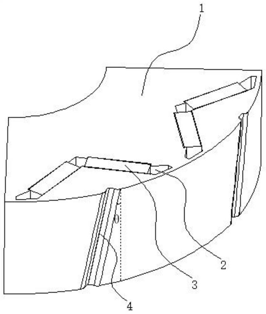
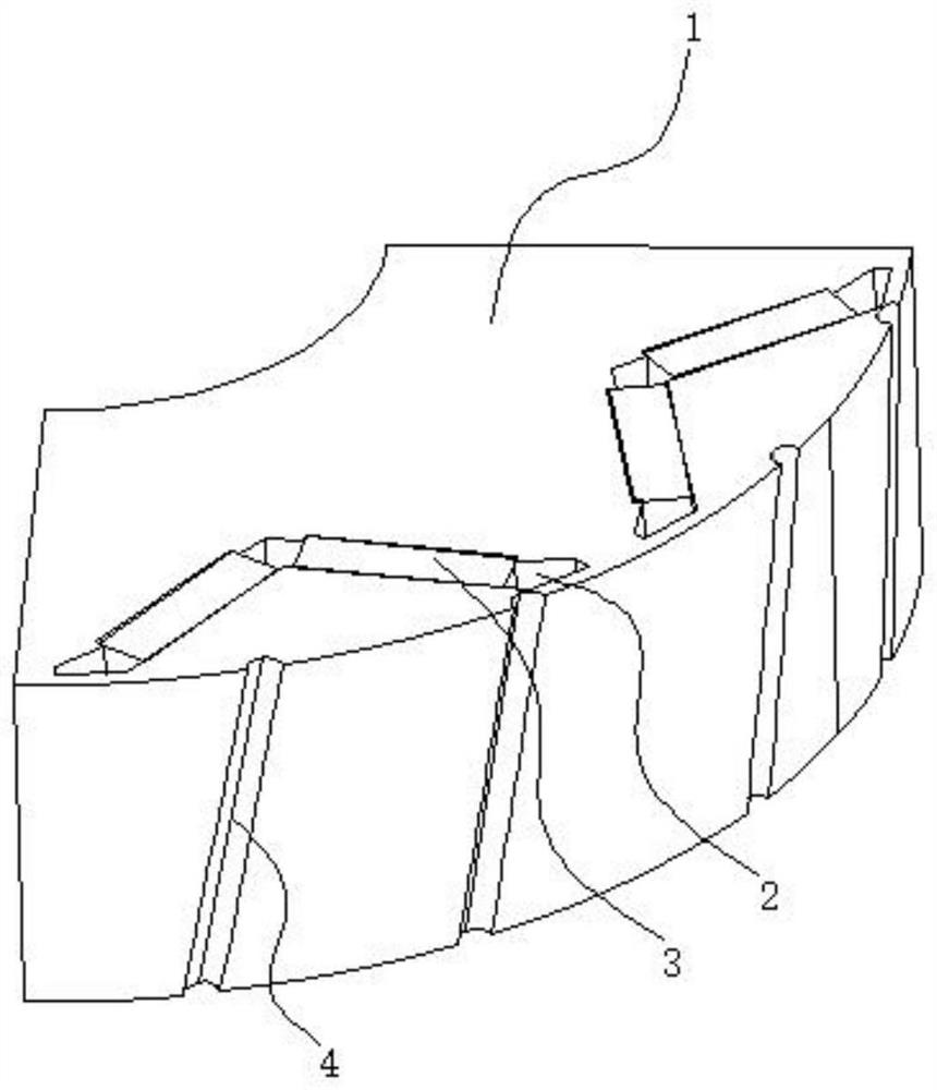
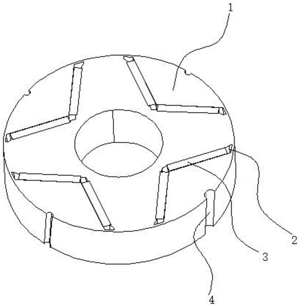
The invention discloses a rotor for a permanent magnet synchronous motor and the permanent magnet synchronous motor. The rotor for the permanent magnet synchronous motor comprises a rotor iron core, the rotor iron core is provided with a plurality of magnetic pole grooves extending along the axial direction, and permanent magnets extending along the axis are arranged in the magnetic pole grooves; the outer surface of the rotor core is provided with a plurality of auxiliary grooves, and the auxiliary grooves and the magnetic pole grooves are mutually independent; and the auxiliary groove has a deviation angle. By adopting the scheme, the cogging torque of the motor can be reduced, the air gap flux density waveform can be corrected, the sine degree of the back electromotive force waveform can be improved, noise vibration caused by defects of the motor body can be reduced, and the electromagnetic performance of the motor can be improved. According to the scheme, the increase of assembly procedures caused by a traditional rotor skewed pole can be avoided, meanwhile, the structural strength of the motor rotor punching sheet is not influenced, more effects of selecting the position and the axial shape of the auxiliary groove are not influenced, and in some specific positions, the noise and vibration performance of the motor can be improved, and the output of the motor is not reduced or even improved.

Description

technical field [0001] The present invention relates to the technical field of rotors, in particular to a rotor for permanent magnet synchronous motors and permanent magnet synchronous motors. Background technique [0002] At present, the permanent magnet synchronous motor has cogging torque and no-load back EMF due to the existence of the permanent magnet in the rotor. The amplitude of the cogging torque and the THD value of the no-load back EMF affect the noise and vibration of the motor to a certain extent. Usually, the cogging torque amplitude and THD can be weakened by means such as rotor skew poles, stator skew slots, unequal air gaps, auxiliary slots, etc. When the unequal air gap and auxiliary slot cannot reduce the cogging torque and THD value to the design requirements, it can be used in combination with the rotor slanted pole and the stator slanted slot. The trough is generally a continuous chute method. [0003] When the motor is a centralized winding, the appl...

Claims


Application Information

Patent Timeline
Patent Type & Authority Applications(China)
IPC IPC(8): H02K1/22H02K1/27H02K21/02
CPCH02K1/22H02K1/27H02K21/02H02K2213/03Y02T10/64
Inventor 吴倩楠蔡锋宾
Owner XIAMEN TUNGSTEN
Why Eureka
Eureka Blog
Learn More