Distributed photovoltaic grid-connected protection equipment

A technology for distributed photovoltaics and protection equipment, applied in photovoltaic power stations, photovoltaic power generation, photovoltaic modules, etc., can solve problems such as non-recycling and easy damage in bad weather.

Pending Publication Date: 2022-07-12
靳永红
View PDF0 Cites 0 Cited by
  • Summary
  • Abstract
  • Description
  • Claims
  • Application Information

AI Technical Summary

Problems solved by technology

[0003] However, the existing distributed photovoltaic grid-connected can not be recovered after being exposed to the air for a long time, which makes it easy to be damaged in bad weather

Method used


Image

  • Distributed photovoltaic grid-connected protection equipment
  • Distributed photovoltaic grid-connected protection equipment
  • Distributed photovoltaic grid-connected protection equipment

Examples


Embodiment 1

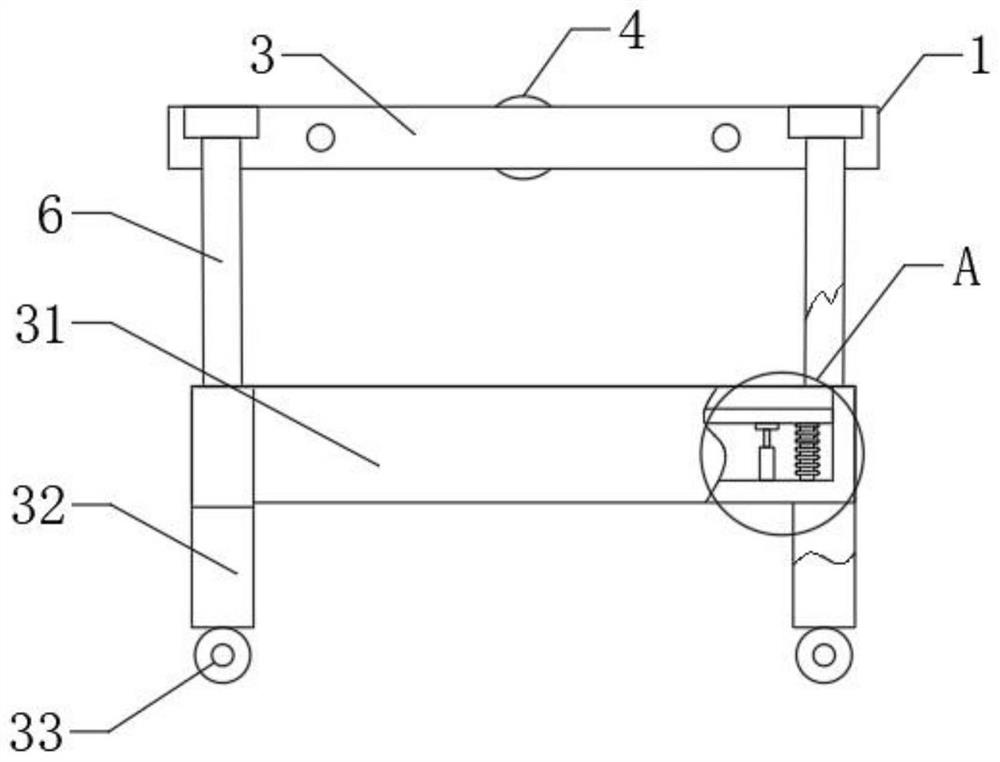
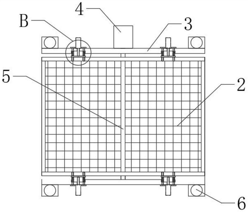
[0031] like Figure 1-6 As shown, the present invention provides a grid-connected protection device based on distributed photovoltaics, including a main device 1, an installation frame 3 is arranged inside the main device 1, a placement box 31 is arranged under the installation frame 3, and a part of the installation frame 3 is arranged. The side is provided with a guide hole 8, the inner wall of the guide hole 8 is movably connected to the limit insertion rod 9, the outer wall of the limit insertion rod 9 is fixedly connected with a fitting plate 11, and the back of the fitting plate 11 is fixedly connected with a buffer spring 10, which is activated by an external power supply. The lateral hydraulic rod 7 drives the lamination plate 11 away from the side of the photovoltaic panel 2, and the lamination plate 11 drives the limit insertion rod 9 to disengage from the inner wall of the lateral insertion hole 12, thereby releasing the restriction on the photovoltaic panel 2. When ...

Embodiment 2

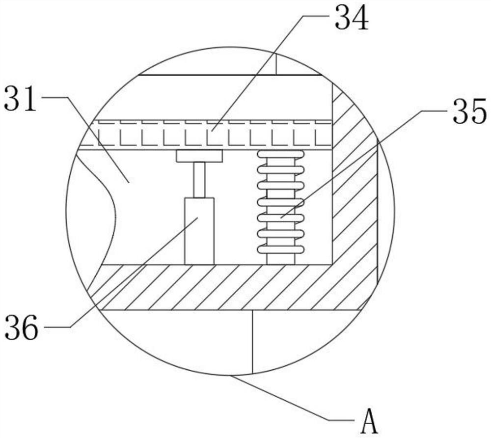
[0034] like Figure 1-6 As shown, on the basis of Embodiment 1, the present invention provides a technical solution: preferably, the side of the photovoltaic panel 2 close to the installation frame 3 is provided with a side jack 12, and one end of the limit insertion rod 9 has an outer wall and a side The inner wall of the socket 12 is movably connected, the inner wall of the damping rod 36 is movably connected with a support rod 37, the top of the support rod 37 is fixedly connected with the bottom surface of the rubber buffer plate 34, and the outer wall of the support rod 37 is fixedly connected with a damping piston 38, the damping piston The upper surface of 38 is provided with a damping hole 39, a damping material 40 is provided below the damping piston 38, and a partition 41 is movably connected to the outer wall of the bottom end of the support rod 37. The universal wheel 33 is used to facilitate movement and realize rapid transfer. The rod 36 absorbs and buffers the v...


PUM


Abstract

The invention discloses distributed photovoltaic grid-connected protection equipment, and relates to the technical field of distributed photovoltaic grid connection, the distributed photovoltaic grid-connected protection equipment comprises a main body device, a mounting frame is arranged in the main body device, a placement box is arranged below the mounting frame, one side of the mounting frame is provided with a guide hole, and the guide hole is communicated with the storage box. The inner wall of the guide hole is movably connected with a limiting insertion rod, the outer wall of the limiting insertion rod is fixedly connected with an attaching plate, and the back face of the attaching plate is fixedly connected with a buffer spring. Limiting inserting rods are driven by side hydraulic rods to be separated from the inner walls of side inserting holes, limitation on a photovoltaic panel is relieved, a rotating motor drives the photovoltaic panel to turn over by a circle through a linkage rod, a lifting hydraulic rod is started to drive a mounting frame to move downwards, and the mounting frame drives the photovoltaic panel to move downwards into a containing box. One side of the mounting frame is attached to the outer wall of the placement box, the bottom surface of the photovoltaic panel is attached to the upper surface of the rubber buffer plate, and the placement box is matched with the back surface of the photovoltaic panel to form protection.

Description

technical field [0001] The invention relates to the technical field of distributed photovoltaic grid connection, in particular to a protection device based on distributed photovoltaic grid connection. Background technique [0002] Photovoltaic is the abbreviation of solar photovoltaic power generation system. It is a new type of power generation system that uses the photovoltaic effect of solar cell semiconductor materials to directly convert solar radiation energy into electrical energy. There are two modes of independent operation and grid-connected operation. The classification of solar photovoltaic power generation systems, one is centralized, such as large-scale northwest ground photovoltaic power generation systems; the other is distributed (with >6MW as the boundary), such as industrial and commercial enterprise plant roof photovoltaic power generation systems, residential roof photovoltaic power generation systems, distributed Photovoltaic power generation refers ...

Claims


Application Information

Patent Timeline
Patent Type & Authority Applications(China)
IPC IPC(8): H02S20/30H02S10/40H02S30/10F16F15/08H02J3/38
CPCH02S20/30H02S10/40H02S30/10F16F15/08H02J3/381H02J2300/24Y02E10/56
Inventor 靳永红
Owner 靳永红
Why Eureka
Try Eureka