Plug-in type communication base station convenient to install

A communication base station and plug-in technology, which is applied in the field of plug-in communication base stations, can solve the problems of inconvenient installation of communication base stations, and achieve the effect of fast installation and low labor intensity

Pending Publication Date: 2022-07-15
浙江德宝通讯科技股份有限公司
View PDF1 Cites 0 Cited by
  • Summary
  • Abstract
  • Description
  • Claims
  • Application Information

AI Technical Summary

Problems solved by technology

[0005] The invention solves the problem of inconvenient installation of communication base stations in the prior art, and provides a plug-in communication system that does not require hoistin

Method used


Image

  • Plug-in type communication base station convenient to install
  • Plug-in type communication base station convenient to install
  • Plug-in type communication base station convenient to install

Examples


Example Embodiment

[0023] Example 1:

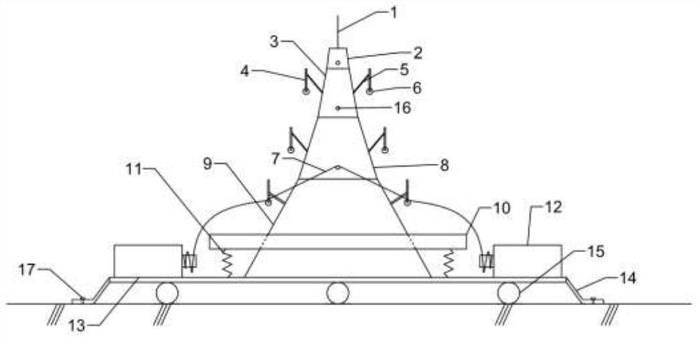
[0024] A plug-in communication base station that is easy to install, such as figure 1 As shown, it includes a main body and a base. The main body includes a first main body segment 2, a second main body segment 3, a third main body segment 8 and a fourth main body segment 9 that are inserted in sequence from top to bottom. The upper end of the first main body segment 2 A lightning rod 1 is connected, a machine room 10 is built on the fourth main body section 9 , and the lower end of the fourth main body section 9 is connected to a base, which includes a base bearing plate 13 , a bracket 14 and a pulley 15 . The base bearing plate 13 is connected to the lower end of the fourth main body section 9 for carrying the main body of the communication base station. The side of the base carrying plate 13 facing away from the fourth main body section 9 is evenly provided with three pulleys 15 . The pulleys 15 are used for the transportation of the base and the main b...

Example Embodiment

[0027] Example 2:

[0028] A plug-in communication base station that is easy to install, such as Figure 4 As shown, it includes a main body and a base. The main body includes a first main body segment 2, a second main body segment 3, a third main body segment 8 and a fourth main body segment 9 that are inserted in sequence from top to bottom. The upper end of the first main body segment 2 A lightning rod 1 is connected, a machine room 10 is built on the fourth main body section 9 , the lower end of the fourth main body section 9 is connected to the base, and the base includes a base bearing plate 13 , a bracket 14 and a pulley 15 . The base bearing plate 13 is connected to the lower end of the fourth main body section 9 for carrying the main body of the communication base station. The side of the base carrying plate 13 facing away from the fourth main body section 9 is evenly provided with three pulleys 15 . The pulleys 15 are used for the transportation of the base and the ...


PUM


Abstract

The invention discloses a plug-in type communication base station convenient to install, and aims to provide a plug-in type communication base station which is low in installation cost and high in installation speed. Comprising a main body and a base, the main body comprises main body sections which are sequentially connected in an inserted mode, one end of the main body is connected with a lightning rod, the other end of the main body is connected with the base, and the main body sections are connected with insertion equipment. The plug-in equipment comprises a lifting device and a power transmission device, and the plug-in equipment is connected with a motor. The shape of the main body section is a circular truncated cone. In every two adjacent main body sections, the ratio of the diameter of the tail end of the upper main body section to the diameter of the top end of the lower main body section is larger than 1, so that the lower main body section is inserted into the upper main body section. And the ratio of the length of the lower main body section inserted into the upper main body section to the height of the upper main body section ranges from 0.25 to 0.75. According to the invention, the installation speed of the communication base station is improved, and the installation labor intensity of the communication base station is reduced.

Description

technical field [0001] The invention relates to the field of communication base stations, in particular to a plug-in communication base station that is easy to install. Background technique [0002] A base station is a public mobile communication base station, which is an interface device for mobile devices to access the Internet, and is also a form of radio station. Passed radio transceiver station. The construction of mobile communication base stations is an important part of the investment of mobile communication operators. The construction of mobile communication base stations is generally carried out around such elements as coverage, call quality, investment efficiency, ease of construction, and ease of maintenance. With the development of mobile communication network services in the direction of dataization and packetization, the development trend of mobile communication base stations must also be broadband, large-coverage construction and IP-based. [0003] Most of ...

Claims


Application Information

Patent Timeline
IPC IPC(8): E04H12/00E04H12/18
CPCE04H12/00E04H12/18
Inventor 刘欣张平陈建明陈江棋陈永军徐养松
Owner 浙江德宝通讯科技股份有限公司
Why Eureka
Try Eureka