Unlock instant, AI-driven research and patent intelligence for your innovation.

Energy-saving waste heat utilization waste incineration system

A technology of waste incineration and waste heat, applied in the direction of incinerator, combustion type, combustion method, etc., can solve the problems of waste of resources, reduce combustion efficiency, high thermal pressure, etc., and achieve the effect of improving combustion efficiency, realizing combustion and fully burning

Pending Publication Date: 2022-07-15
林伟森
View PDF1 Cites 0 Cited by
  • Summary
  • Abstract
  • Description
  • Claims
  • Application Information

AI Technical Summary

Problems solved by technology

[0004] 1. This prior art achieves the driving effect by adding water to the steam chamber and heating the water with the incineration of garbage to generate steam to drive the turbofan to rotate. The disadvantage of this is that the heat exchange area between the steam chamber and the waste heat is too small , so that most of the energy for heating the steam chamber comes from the energy of incinerating garbage, and this part of energy is mainly provided by natural resources, that is, the existing technology achieves additional effects by wasting resources, and cannot really achieve energy-saving effects;
[0005] 2. The exhaust gas and the intake air are in the same opening, and the large heat generated by incineration will make the thermal pressure in the incineration chamber larger, so that the exhaust gas and the intake air cannot be separated well, which will affect the normal oxygen supply of incineration , so as to reduce the combustion efficiency, and the exhaust gas will be discharged directly without treatment, which will also cause a large degree of pollution. Based on this, the present invention designs an energy-saving waste heat utilization waste incineration system

Method used


Image

  • Energy-saving waste heat utilization waste incineration system
  • Energy-saving waste heat utilization waste incineration system
  • Energy-saving waste heat utilization waste incineration system

Examples


Embodiment Construction

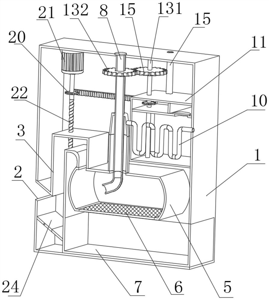
[0023] refer to Figure 1-4 , a waste incineration system for energy-saving waste heat utilization, comprising a case 1, a feed port 2 is provided on one side of the case 1, a feed pipe 3 is sealed and fixedly connected at the feed port 2, and the cross section of the feed pipe 3 is set to A square structure, the other end of the feed pipe 3 is fixedly connected with a combustion box 5, the combustion box 5 is provided with a communication port 4 that communicates with the feed pipe 3, and the bottom of the combustion box 5 is fixedly provided with an ash filter 6. A collection box 7 is arranged below the ash filter screen 6, and a vibrating plate can be optionally arranged in the ash filter screen 6 to completely shake off the burning ash on the ash filter screen 6 into the collection box 7, and the bottom wall of the collection box 7 is slidably connected. On the inner bottom wall of the case 1, it can be drawn out, so that the burning ash can be centrally treated. An openin...


PUM


Abstract

The energy-saving waste heat utilization waste incineration system comprises a machine box, a feeding opening is formed in one side of the machine box, a feeding pipeline is fixedly connected to the feeding opening in a sealed mode, a combustion box is fixedly connected to the other end of the feeding pipeline, a communication opening communicating with the feeding pipeline is formed in the combustion box, and a waste heat utilization device is arranged in the communication opening. An ash filtering net is fixedly arranged at the bottom of the combustion box, a material collecting box is arranged below the ash filtering net, the bottom wall of the material collecting box is slidably connected to the inner bottom wall of the machine box, an opening is formed in the center of the top of the combustion box in a penetrating mode, an air outlet pipe is fixedly connected to the opening in a sealed mode, and the air outlet pipe is connected with a waste heat preheating structure; and a batch feeding structure is connected in the feeding pipeline. The device has the advantages that the situation that external air with low temperature enters the combustion process and needs to consume energy to heat the part of air is avoided, so that heat is fully utilized, and sufficient combustion is achieved through batch feeding.

Description

technical field [0001] The invention relates to the technical field of waste incineration, in particular to a waste incineration system for energy-saving waste heat utilization. Background technique [0002] When people conduct waste incineration, the heat generated by the incineration is usually directly discharged through the exhaust gas, so that this part of the waste heat resources is wasted. However, in the prior art, the waste heat is used for power generation, and the efficiency is low. [0003] After searching, the Chinese authorized patent publication number CN110186049B discloses a waste incineration system, which includes a body, an incineration cavity and a feeding cavity arranged in the body, and a flue is arranged in the top wall of the incineration cavity. There is a steam cavity around the circumferential wall of the flue. The equipment can use the same power source to realize the equipment feeding and ash screening, which simplifies the equipment structure. ...

Claims


Application Information

Patent Timeline
Patent Type & Authority Applications(China)
IPC IPC(8): F23G7/00F23G5/46F23G5/44F23L15/00F23J15/06F23J1/00
CPCF23G7/00F23G5/46F23G5/44F23L15/00F23J15/06F23J1/00
Inventor 林伟森
Owner 林伟森