Commutation failure detection method and device based on commutation inductor energy change rate

A technology of energy change and commutation failure, applied to emergency protection circuit devices, electrical components, fault locations, etc., can solve the problems of low judgment accuracy and achieve low speed and accuracy, easy implementation, and fast and accurate detection Effect

Pending Publication Date: 2022-07-15
NORTH CHINA ELECTRIC POWER UNIV (BAODING)
View PDF0 Cites 0 Cited by
  • Summary
  • Abstract
  • Description
  • Claims
  • Application Information

AI Technical Summary

Problems solved by technology

[0005] In view of the above analysis, the embodiment of the present invention aims to provide a commutation failure detection method and device based on the energy change rate of the commutation inductance to solve the problem of low judgment accuracy in the existing commutation failure judgment method

Method used


Image

  • Commutation failure detection method and device based on commutation inductor energy change rate
  • Commutation failure detection method and device based on commutation inductor energy change rate
  • Commutation failure detection method and device based on commutation inductor energy change rate

Examples


Embodiment 1

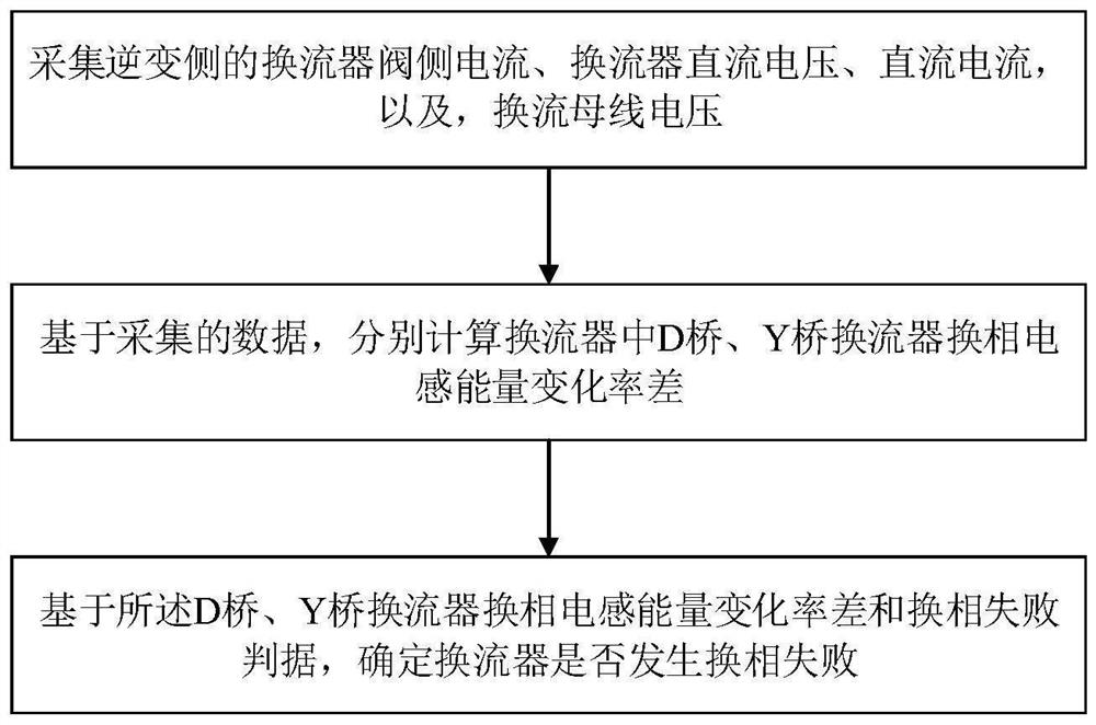
[0071] A specific embodiment of the present invention discloses a commutation failure detection method based on the rate of change of commutation inductance energy, such as: figure 1 shown, including the following steps:

[0072] S1. Collect the inverter valve side current, the inverter DC voltage, the DC current, and the commutation bus voltage on the inverter side;

[0073] S2. Based on the collected data, calculate the energy change rate difference of the commutation inductance of the D-bridge and Y-bridge converters in the converter respectively;

[0074] S3. Based on the commutation inductance energy change rate difference and commutation failure criterion of the D-bridge and Y-bridge converters, determine whether a commutation failure occurs in the converter.

[0075] Specifically, the converter is an inverter-side 12-pulse converter.

[0076] During implementation, in step S2, based on the collected data, the difference in the energy change rate of the commutation ind...

Embodiment 2

[0271] A specific embodiment 2 of the present invention provides a commutation failure detection device based on the rate of change of commutation inductance energy, such as: Figure 5 shown, including:

[0272] The data acquisition module is used to collect the inverter valve side current, the inverter DC voltage, the DC current, and the commutation bus voltage on the inverter side;

[0273] The commutation inductance energy change rate difference calculation module is used to calculate the commutation inductance energy change rate difference of the D-bridge and Y-bridge converters in the converter based on the collected data;

[0274] A commutation failure judging module is configured to determine whether a commutation failure occurs in the converter based on the difference in the rate of change of the commutation inductance energy of the D-bridge and Y-bridge converters and the commutation failure criterion.

[0275] When implementing, described based on the data collected...

Embodiment 3

[0286] In order to verify the correctness of the commutation failure detection method and device based on the rate of change of commutation inductance energy provided in Embodiments 1 and 2 of the present invention, this embodiment tests the solutions in the above-mentioned embodiments. Table 1 shows the main parameters of the HVDC transmission system.

[0287] Table 3 Main parameters of HVDC transmission system

[0288]

[0289] Scenario 1 is set in this example: A phase-to-earth fault is set on the AC line, and the transition resistance varies from 0 to 300Ω. The current changes of the D-bridge and Y-bridge converter valves under the above fault conditions are as follows: Image 6 shown.

[0290] Depend on Image 6 (a) It can be seen that when the transition resistance is 0-200Ω, the commutation failure of the D-bridge converter occurs. Among them, when the transition resistance is 0~100Ω, the pre-shut-off converter valve VD3 is continuously turned on; when the transi...


PUM


Abstract

The invention relates to a commutation failure detection method and device based on a commutation inductor energy change rate, belongs to the technical field of relay protection, and solves the problem of low judgment accuracy of a commutation failure judgment method in the prior art. The method comprises the following steps: collecting a converter valve side current, a converter DC voltage, a DC current and a converter bus voltage at an inversion side; based on the collected data, respectively calculating the commutation inductance energy change rate difference of the D-bridge converter and the Y-bridge converter in the converter; and based on the commutation inductance energy change rate difference of the D-bridge converter and the Y-bridge converter and the commutation failure criterion, determining whether the commutation failure occurs in the converter. According to the invention, commutation failure discrimination is realized, and the discrimination accuracy of commutation failure is improved.

Description

technical field [0001] The invention relates to the technical field of relay protection, in particular to a commutation failure detection method and device based on the rate of change of commutation inductance energy. Background technique [0002] With the improvement of the voltage level and transmission power of the HVDC transmission system, the probability of commutation failure of the inverter side converters gradually increases. Since the occurrence of commutation failure will cause the transmission power of the DC system to drop, the subsequent continuous commutation failure may even lead to interruption of power transmission and then cause DC blocking, which seriously threatens the safe and stable operation of the DC transmission system. Therefore, judging the commutation failure is of great significance to the safe operation of the actual system, and lays a foundation for the subsequent elimination of the influence of the commutation failure on the system. [0003] ...

Claims


Application Information

Patent Timeline
Patent Type & Authority Applications(China)
IPC IPC(8): G01R31/08H02J3/36H02H7/26
CPCG01R31/085H02J3/36H02H7/268
Inventor 马静赵文越刘晨介贺彤马瑞辰王增平
Owner NORTH CHINA ELECTRIC POWER UNIV (BAODING)
Why Eureka
Try Eureka