Ball bead supporting bridging sample anti-blocking drainage device for vacuum sealing drainage

A technology of supporting bridges and balls, applied in the direction of suction devices, dressings, viscous dressings, etc., can solve the problems of weakening the effect and efficiency of VSD devices, poor negative pressure conduction, difficulty in suction, etc., and achieve the possibility of compressive necrosis of tissue cells Sexual weakening, continuous effective continuous rebound, continuous effective drainage effect

Pending Publication Date: 2022-07-22
程虎
View PDF0 Cites 0 Cited by
  • Summary
  • Abstract
  • Description
  • Claims
  • Application Information

AI Technical Summary

Problems solved by technology

[0009] However, there are also relatively large defects in clinical application at present, mainly manifested as: hydrophilic porous foam materials are easy to dry and harden due to dehydration after 2-4 days of clinical application, resulting in a decrease in the resilience of the material and effective drainage of the cavity Reduced significantly, permeability decreased, gradually blocked, and under the action of pus, tissue fluid, exudate, blood and other organic colloids, foam material pores often adhered, and the elasticity decreased and could not rebound... All of the above weakened the impact of the VSD device on Effectiveness and efficiency of wound repair therapy
[0010] In the prior art, someone proposed a structure in which the upper straight columnar support column group and the perforated panel constitute a multi-cavity groove network, but because the straight columnar column is too slender in this structure, there is a problem that the straight columnar support column group is stressed. It is easy to be skewed and misplaced and inserted into the drainage hole to cause blockage; some people have proposed a three-layer honeycomb multi-cavity anti-blocking and anti-collapse wound drainage device, but this three-layer structure has too much space, which will easily lead to poor negative pressure conduction and dead volume. Difficulty in suctioning when there is a lot, medium or small amount of exudate

Method used


Image

  • Ball bead supporting bridging sample anti-blocking drainage device for vacuum sealing drainage
  • Ball bead supporting bridging sample anti-blocking drainage device for vacuum sealing drainage
  • Ball bead supporting bridging sample anti-blocking drainage device for vacuum sealing drainage

Examples


Embodiment 1

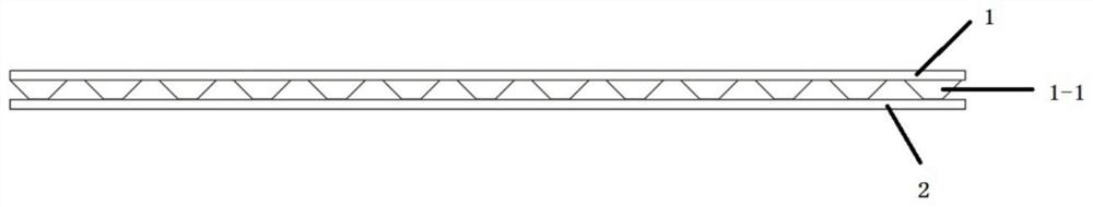
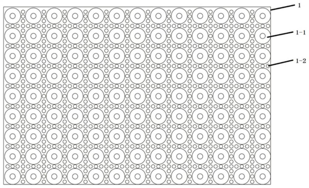
[0055] like Figures 1 to 3 As shown, this embodiment is a preferred structure, specifically a ball-supported bridge-like anti-blocking and drainage device for negative pressure closed drainage, including an upper support layer 1 and a lower drainage layer 2; the upper support layer 1 is evenly distributed There are a plurality of drainage holes 1-2, the upper surface of which is a smooth plane, which is easy to be sealed with a medical sealing film, and a plurality of ball supports 1-1 are evenly distributed on the lower surface, the ball supports 1-1 and the lower drainage layer 2 The radius of the circular bottom surface of the opposite lower surface is smaller than the radius of the circular bottom surface of the upper surface, thereby forming a downwardly convex truncated cone, and the drainage holes 1-2 are evenly distributed around the ball support 1-1.

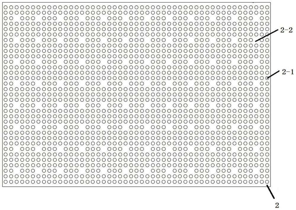
[0056] The lower drainage layer 2 is evenly distributed with a plurality of supporting surfaces 2-2, the supporting ...

Embodiment 2

[0068] like Figures 6 to 7 As shown in the figure, another preferred structure is proposed in this embodiment. The difference from Embodiment 1 lies in that the supporting surface 2-2 of the lower drainage layer 2 is provided with connecting holes 2-3, and the balls of the upper supporting layer 1 support the 1- The lower surface of 1 is embedded in the connection holes 2-3, and is fixed with the lower drainage layer 2, which can not only play a supporting role, but also ensure smoothness and no blockage.

[0069] Since the supporting surface 2-2 of the lower drainage layer 2 of this structure is provided with a connecting hole 2-3, and the lower surface of the ball support 1-1 of the upper supporting layer 1 is embedded in the connecting hole 2-3, the upper and lower parts of the structure are When the layers are combined, the overall thickness is 1 mm less than the structure of Example 1, which is 4 mm thick. This design has the following three beneficial effects: 1. The l...

Embodiment 3

[0071] like Figures 8 to 9 As shown in the figure, another preferred structure is proposed in this embodiment. The difference from Embodiment 1 is that the middle part of the ball support 1-1 of the upper support layer 1 is provided with a connecting groove 1-3, and the support surface 2 of the lower drainage layer 2 is provided with a connecting groove 1-3. -2 is provided with a connecting body 2-4, the connecting body 2-4 is embedded in the connecting groove 1-3 to limit and fix, which plays a supporting role and ensures smoothness and no blockage.

[0072] Since the middle part of the ball support 1-1 of the upper support layer 1 is provided with a connecting groove 1-3, the supporting surface 2-2 of the lower drainage layer 2 is provided with a connecting body 2-4, and the connecting body 2-4 is embedded in the connecting groove 1 -3 The inner limit is fixed, so the structure has the following two beneficial effects: 1. The limit effect is stronger than that of Embodiment...


PUM


Abstract

The invention discloses a ball support bridging sample anti-blocking drainage device for vacuum sealing drainage. The ball support bridging sample anti-blocking drainage device comprises an upper support layer and a lower drainage layer, ball supports and drainage holes which are uniformly distributed are formed in the surface of the upper supporting layer, and the drainage holes are through holes and are staggered with the ball supports; the surface of the lower drainage layer is provided with drainage through holes which are uniformly distributed, and the drainage through holes correspond to the drainage holes. By the adoption of the porous multi-support double-layer design, under the effective negative pressure condition, structural collapse is avoided, drainage is smooth, blockage is avoided, the PVA material hardly becomes dry and hard, rebound resilience and permeability are greatly improved, sealing and flushing are easy, drainage is easy, and the treatment effect and efficiency are remarkably improved.

Description

technical field [0001] The invention belongs to the technical field of negative pressure sealing and drainage, in particular to a ball-supported bridge-like anti-blocking drainage device used for negative pressure sealing and drainage. Background technique [0002] In 1994, Professor Qiu Huade applied Vacuum Sealing Drainage (VSD for short) to general surgery for the first time, creating a precedent for the application of negative pressure sealing drainage technology in general surgery in China. [0003] Existing VSD technology, its basic configuration includes medical hydrophilic foam material or medical hydrophobic foam material (hereinafter collectively referred to as porous foam material for the above medical materials), sealing film, drainage pipeline, collection container and negative pressure source (including medical suction machine, hospital center negative pressure device or negative pressure drainage bottle, etc.). By applying continuous or intermittent negative ...

Claims


Application Information

Patent Timeline
Patent Type & Authority Applications(China)
IPC IPC(8): A61M1/00A61F13/02
CPCA61F13/0216A61F13/00017A61F13/00029A61F13/00068
Inventor 程虎
Owner 程虎
Why Eureka
Try Eureka