Pretreatment distillation device and method for continuous regeneration of waste lubricating oil

A technology of waste lubricating oil and distillation equipment, which is applied in the direction of vacuum distillation, separation method, lubricating composition, etc., can solve the problems of the reduction of continuous operation efficiency of distillation equipment and the decrease of fraction effect, and achieve the improvement of continuous operation efficiency, increase of fraction effect, The effect of improving distillation efficiency

Active Publication Date: 2022-07-22
东营国安化工有限公司
View PDF10 Cites 2 Cited by
  • Summary
  • Abstract
  • Description
  • Claims
  • Application Information

AI Technical Summary

Problems solved by technology

[0006] Aiming at the deficiencies of the prior art, the present invention provides a pretreatment distillation device and method for continuous regeneration of waste lubricating oil, which solves the problem that the existing waste lubricating oil distillation treatment equipment cannot effectively clean the coking on the inner wall of the distillation tower, resulting in distillation The effect of the distillate in the application of continuous regeneration pretreatment of waste lubricating oil in the tower is reduced, and the continuous operation efficiency of the distillation unit is reduced

Method used


Image

  • Pretreatment distillation device and method for continuous regeneration of waste lubricating oil
  • Pretreatment distillation device and method for continuous regeneration of waste lubricating oil
  • Pretreatment distillation device and method for continuous regeneration of waste lubricating oil

Examples


Embodiment 1

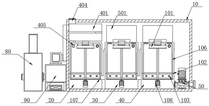
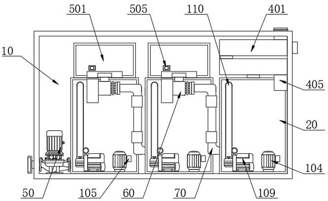
[0040] see Figure 1-2 As shown, a pretreatment distillation device for continuous regeneration of waste lubricating oil includes a cabinet 10, and a first-stage distillation tank 20, a second-stage distillation tank 30 and a third-stage distillation tank 40 are arranged side by side inside the cabinet 10. The right side inside the cabinet 10 A first suction pump 50 is provided, and the feed end of the first suction pump 50 is communicated with the interior of the three-stage distillation tank 40, and the back of the two-stage distillation tank 30 and the third-stage distillation tank 40 is provided with a second pumping material. pump 60, and both ends of the two second suction pumps 60 are connected with oil delivery pipes 70, wherein the two oil delivery pipes 70 of one second suction pump 60 are respectively connected with the primary distillation tank 20 and the secondary distillation tank 30. Internal communication, the two oil delivery pipes 70 of the other second sucti...

Embodiment 2

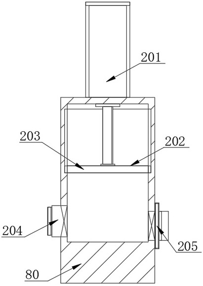
[0043] see Figure 1-3 As shown, in the present invention, one side of the chassis 10 is provided with a material extraction box 80, and the inside of the material extraction box 80 is provided with a material extraction mechanism. The top of the box 80 is fixedly connected, one end of the drive shaft of the servo electric cylinder 201 penetrates the extraction box 80 and extends to the inside of the extraction box 80, and one end of the drive shaft of the servo electric cylinder 201 that extends to the inside of the extraction box 80 is fixedly connected with a movable Plate 202, the surface of the movable plate 202 is covered with a rubber sleeve 203, the surface of the rubber sleeve 203 is slidably connected with the inner wall of the extraction box 80, and the drive shaft of the servo electric cylinder 201 is used to drive the movable plate 202 to slide up and down inside the extraction box 80 According to the sliding stroke of the drive shaft of the servo electric cylinde...

Embodiment 3

[0045] see Figure 1-4 As shown, in the present invention, a separation box 90 is arranged between the chassis 10 and the extraction box 80, and a separation mechanism is arranged inside the separation box 90. The separation mechanism includes a separation frame 301, and the two sides of the separation frame 301 are connected to the separation box 90. The interior of the separation frame 301 is fixedly connected, the separation frame 301 is provided with a separation screen 302, and the top of the separation frame 301 is provided with electric push rods 303 on both sides. To the bottom of the separation frame 301, and the surface of the separation frame 301 is sleeved with a movable frame 304, the two sides of the top of the movable frame 304 are respectively fixedly connected with the bottom ends of the two electric push rods 303 drive shafts, and the interior of the movable frame 304 is arranged There is a sponge block 305, the inner surface of the sponge block 305 is in con...


PUM


Abstract

The invention relates to the technical field of waste lubricating oil pretreatment, in particular to a pretreatment distillation device and method for continuous regeneration of waste lubricating oil, the pretreatment distillation device comprises a case, and a first-stage distillation retort, a second-stage distillation retort and a third-stage distillation retort are arranged in the case side by side; meanwhile, distillation mechanisms are arranged in the multiple stages of distillation retorts, vacuum distillation treatment is conducted on the waste lubricating oil in the first-stage distillation retort, the second-stage distillation retort and the third-stage distillation retort in sequence, gas is blown into the waste lubricating oil in the vacuum distillation process of the waste lubricating oil, bubbles are continuously blown out of the interior of the waste lubricating oil, and the waste lubricating oil is continuously discharged. According to the waste lubricating oil distillation device, on one hand, the distillation efficiency of waste lubricating oil can be improved, on the other hand, an oil film is prevented from being formed in the distillation process, meanwhile, coke on the inner wall of the distillation retort is cleaned through the scraping frame and the scraping plate in the distillation treatment process, and the continuous operation efficiency of the distillation device is improved while the fraction effect of the waste lubricating oil is guaranteed.

Description

technical field [0001] The invention relates to the technical field of waste lubricating oil pretreatment, in particular to a pretreatment distillation device and method for continuous regeneration of waste lubricating oil. Background technique [0002] Lubricating oil is one of the important means to control friction and reduce wear in mechanical devices. It is widely used in occasions requiring mechanical operation. It is called the blood of machinery. Lubricating oil is a product with high added value extracted from petroleum. It is composed of lubricating base oil and lubricating oil additives, among which the mass fraction of base oil is 70% to 98%. Unlike fuel oil, which has substantial loss during use, the physical and chemical properties are caused by the continuous increase of impurities. Change and can not continue to use, become waste lubricating oil; [0003] The invention patent with publication number CN108211406A discloses a vacuum distillation equipment for ...

Claims


Application Information

Patent Timeline
Patent Type & Authority Applications(China)
IPC IPC(8): B01D3/10B01D29/35B01D29/64C10M175/00
CPCB01D3/10B01D29/35B01D29/64C10M175/0033Y02W30/74
Inventor 王春妹陈学军
Owner 东营国安化工有限公司
Why Eureka
Try Eureka