Check patentability & draft patents in minutes with Patsnap Eureka AI!

Dust removal structure for mechanical finish machining grinding device and using method of dust removal structure

A technology of machinery and dust intake, applied in the field of mechanical finishing, can solve the problems of unfavorable flying dust collection, easy to cause dust, blockage at the inlet, etc., and achieve the effect of expanding the scope of dust collection and improving work efficiency.

Active Publication Date: 2022-07-22
杭州文林机械有限公司
View PDF6 Cites 0 Cited by
  • Summary
  • Abstract
  • Description
  • Claims
  • Application Information

AI Technical Summary

Problems solved by technology

[0005] The object of the present invention is to provide a dust removal structure for a mechanical finishing grinding device and its use method, which solves the problem of collecting fly dust in the current dust removal device in the background technology. During the process, a large amount of flying dust will stick to the inlet. With the accumulation of time, the flying dust at the inlet will continue to accumulate, resulting in blockage of the inlet, affecting the subsequent entry of flying dust, and delaying work efficiency. Secondly, in the dust collection process In the middle, it is easy to cause dust phenomenon, which will have an adverse effect on the working environment, and is not conducive to the collection of fly dust, which will reduce the quality of fly dust collection.

Method used


Image

  • Dust removal structure for mechanical finish machining grinding device and using method of dust removal structure
  • Dust removal structure for mechanical finish machining grinding device and using method of dust removal structure
  • Dust removal structure for mechanical finish machining grinding device and using method of dust removal structure

Examples


Embodiment approach

[0056] In order to further explain the above embodiments better, the present invention also provides an embodiment, a method for using a dust removal structure for a mechanical finishing grinding device, comprising the following steps:

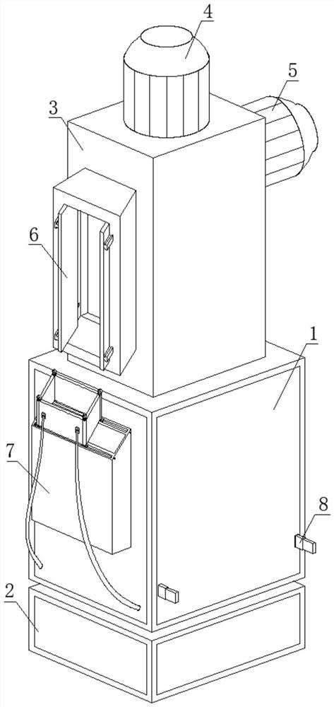
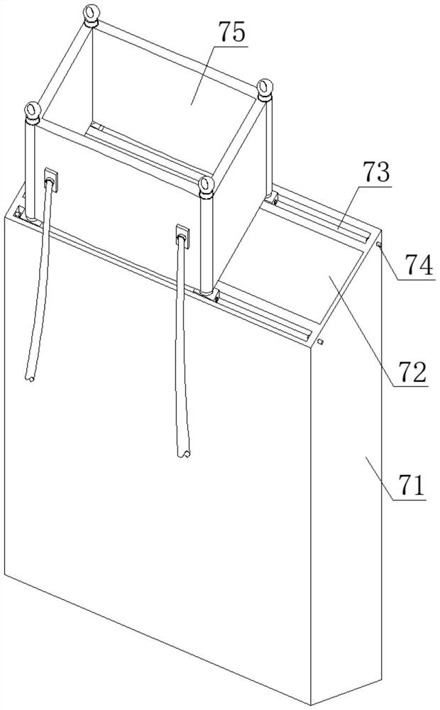
[0057] S1: During the grinding process, place the whole at the grinding device, align the dust intake mechanism 6 with the grinding part of the parts, start the main air pump B5 at the same time, and pull out the display plate 62 from the feeding box 61 to expand the dust suction range;

[0058] S2: The inhaled flying dust will gradually accumulate on the placement plate 91. With the continuous accumulation of the flying dust, the overall weight of the placement plate 91 will increase, the placement plate 91 will move down along the wall groove 33, and the ejector rod 343 will push up The center block 95 is opened, and the lower bottom surface of the placement plate 91 will touch the control switch 341, so that the main air pump A4 is turned on...


PUM


Abstract

The invention discloses a dust removal structure for a mechanical finish machining polishing device and a using method of the dust removal structure, belongs to the technical field of mechanical finish machining, and aims to solve the problems that in the existing flying dust blowing process, the dust raising phenomenon is easily caused, flying dust collection is not facilitated, the flying dust collection quality is reduced, and adverse effects are caused on the personal safety of workers. Through the dust inlet mechanism, the dust collection mechanism, the external insertion assembly and the built-in mechanism, the dust inlet box is connected with the dust inlet mechanism and the built-in mechanism, and the main box body is connected with the dust collection mechanism and the external insertion assembly; with continuous accumulation of flying dust and increase of the overall weight of the placement plate, the placement plate can move downwards along the wall groove, the lower bottom face of the placement plate can make contact with a control switch, so that a main air pump A is turned on, when the main air pump A is turned on, local airflow enters a short connecting pipe and is sprayed out from an inclined blowing plate, and dust is blown out from the inclined blowing plate; flying dust adhered to the surface of the display board is cleaned, the display board is prevented from being blocked by the flying dust, and the working efficiency is indirectly improved.

Description

technical field [0001] The invention relates to the technical field of mechanical finishing, in particular to a dust removal structure for a mechanical finishing grinding device and a method for using the same. Background technique [0002] Machining refers to the process of changing the dimensions or properties of a workpiece through a mechanical device. According to the difference in processing methods, it can be divided into cutting processing and pressure processing. The production process of the machine refers to the whole process of making products from raw materials (or semi-finished products). For machine production, it includes the transportation and storage of raw materials, production preparation, blank manufacturing, parts processing and heat treatment, product assembly, and debugging, painting and packaging, etc. The content of the production process is very extensive. Modern enterprises use the principles and methods of systems engineering to organize and guid...

Claims


Application Information

Patent Timeline
IPC IPC(8): B24B55/06B24B55/12
CPCB24B55/06B24B55/12
Inventor 许满文
Owner 杭州文林机械有限公司
Features
  • R&D
  • Intellectual Property
  • Life Sciences
  • Materials
  • Tech Scout
  • Unparalleled Data Quality
  • Higher Quality Content
  • 60% Fewer Hallucinations
Learn More