Eureka AIR delivers breakthrough ideas for toughest innovation challenges, trusted by R&D personnel around the world.

Pneumatic sand adding system and method for electric furnace

An electric furnace and pneumatic technology, which is applied in the field of electric furnace pneumatic sanding system, can solve the problems of low operating efficiency, high labor intensity, and low safety, and achieve the effects of simple structure, reduced working intensity, and improved sanding quality

Pending Publication Date: 2022-07-22
MAANSHAN IRON & STEEL CO LTD
View PDF0 Cites 0 Cited by
  • Summary
  • Abstract
  • Description
  • Claims
  • Application Information

AI Technical Summary

Problems solved by technology

[0004] Aiming at the problems existing in the background technology such as high labor intensity, low safety, low operating efficiency, special requirements for the landing point of the drainage sand and waste of drainage sand materials in the existing electric arc furnace drainage sand, the present invention provides a The electric furnace pneumatic sand adding system and sand adding method can effectively reduce the labor intensity of the workers, improve the operation safety and efficiency, improve the smelting rhythm of the electric furnace, ensure the success rate of sand addition, and reduce the waste of drainage sand materials

Method used


Image

  • Pneumatic sand adding system and method for electric furnace
  • Pneumatic sand adding system and method for electric furnace
  • Pneumatic sand adding system and method for electric furnace

Examples


Embodiment 1

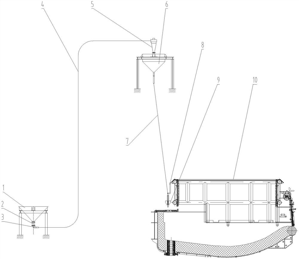
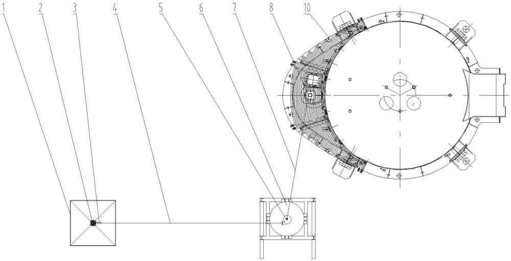
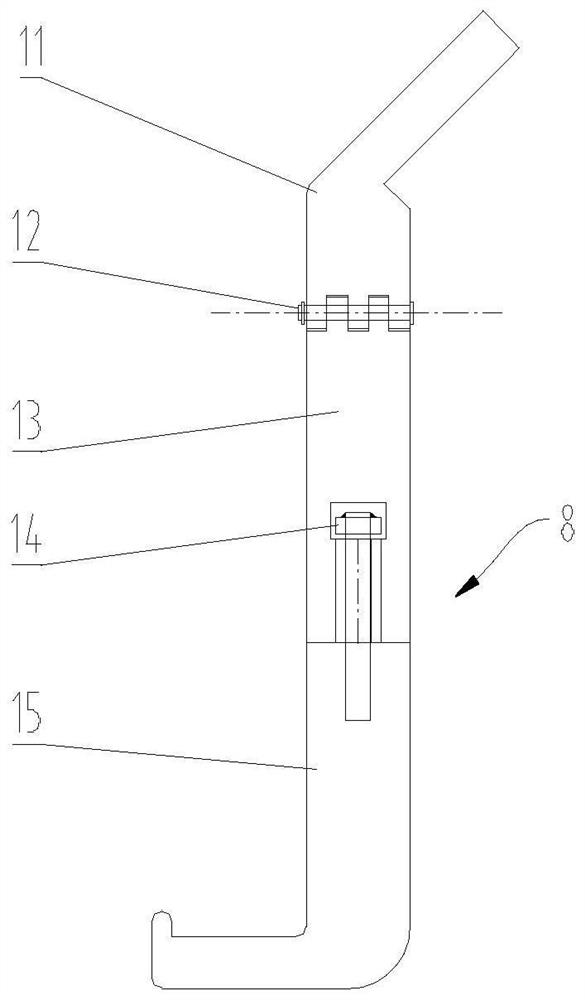
[0033] like Figure 1 to Figure 6 As shown, an electric furnace pneumatic sanding system of the present invention includes a raw material bin 1, an electric furnace 10, a receiving bin 6 located higher than the electric furnace 10, and a furnace shell sanding port (that is, a tapping port) installed on the electric furnace 10. The multi-degree-of-freedom hook device 8 above, the multi-degree-of-freedom hook device 8 is hung with a self-locking sand feeding bucket 9, and the multi-degree-of-freedom hook device 8 can adjust the position with multiple degrees of freedom, thereby driving the self-locking sand feeding bucket 9 hung on it. The position of the sand bucket 9 is adjusted, so that the drainage sand drop point of the self-locking sand filling bucket 9 is aligned with the position of the tapping hole of the electric furnace; the outlet of the raw material bin 1 is connected with a pneumatic conveying mechanism for conveying drainage sand materials, and a pneumatic conveyin...

Embodiment 2

[0039] On the basis of Example 1, as Figure 1-Figure 7 As shown, the electric furnace pneumatic sanding system also includes a controller 28, the tail end of the injector 3 is connected to the compressed air source through a solenoid valve 31, a material level switch 61 is provided on the top of the receiving bin 6, and the lock The gas device 2 , the solenoid valve 31 and the material level switch 61 are respectively connected to the controller 28 through lines. When feeding, when the full signal of the material level switch 61 is transmitted to the controller 28, the controller 28 controls the air lock 2 and the solenoid valve 31 to stop feeding; The motor of the air lock 2 is interlocked to ensure that the material is ventilated and then fed at the beginning of the feeding, and that the material is stopped first and then the gas is stopped after the feeding is completed.

Embodiment 3

[0041] The sanding method of the electric furnace pneumatic sanding system described in embodiment 1 or 2, the steps are as follows:

[0042] S1, feeding: the drainage sand in the raw material warehouse 1 is mixed with the compressed air in the ejector 3 through the air lock 2 to form a gas-solid two-phase fluid, and then the gas-solid two-phase fluid is passed through the feeding pipe 4 is sent to the unloader 5, and the unloader 5 settles the drainage sand in the gas-solid two-phase fluid into the receiving bin 6, and the gas is sucked away by the dust suppression system of the electric furnace itself;

[0043] S2. Sand adding: hang the self-locking sand adding bucket 9 on the multi-degree-of-freedom hook device 8, and then send the drainage sand in the receiving bin 6 to the self-locking sand adding bucket 9 through the hose 7 by its own weight. Through the multi-degree-of-freedom hook device 8, the landing point of the drainage sand is aligned with the position of the tapp...


PUM


Abstract

The pneumatic sand adding system comprises a raw material bin, the electric furnace, a material receiving bin higher than the electric furnace and a multi-degree-of-freedom hook device installed above a sand adding opening of an upper furnace shell of the electric furnace, and a self-locking sand adding hopper is hung on the multi-degree-of-freedom hook device; an outlet of the raw material bin is connected with a pneumatic conveying mechanism, the pneumatic conveying mechanism is connected with the material receiving bin through a material conveying pipe, and an outlet of the material receiving bin is connected with the self-locking sand adding hopper through a hose. The invention mainly solves the problems of high labor intensity of workers, low safety, low operation efficiency, special requirements on the falling point of the stuffing sand, waste of stuffing sand materials and the like when the electric arc furnace stuffing sand is filled in the prior art, effectively reduces the labor intensity of post workers, improves the operation safety and the operation efficiency, promotes the smelting rhythm of the electric furnace, and reduces the production cost. And the sand adding success rate is ensured, and filler sand material waste is reduced.

Description

technical field [0001] The invention belongs to the technical field of electric arc furnace smelting, and particularly relates to an electric furnace pneumatic sanding system and a sanding method. Background technique [0002] In the field of electric arc furnace smelting, the filling operation of tap drainage sand must be carried out after each furnace of steel is smelted in the electric furnace. The operation method usually requires manual transportation of the drainage sand to the sand adding area, and then manual filling operation, which takes a long time to operate. , the filling amount of drainage sand is not easy to control, which affects the smelting rhythm and efficiency of the electric arc furnace, and the filling operation of drainage sand is labor-intensive, coupled with high temperature and dust in the on-site environment, which is not conducive to the occupational health of post personnel. In addition, if the smelting process requires the amount of steel to be ...

Claims


Application Information

Patent Timeline
IPC IPC(8): B65G43/08B65G47/19B65G53/50B65G53/06F27D3/00
CPCB65G43/08B65G47/19B65G53/50B65G53/06F27D3/0033B65G2201/045Y02P10/20
Inventor 李保运曹天明苏炜尹平戴本俊杨帆
Owner MAANSHAN IRON & STEEL CO LTD
Why Eureka
Eureka Blog
Learn More