Energy-saving sewage treatment equipment
A kind of sewage treatment equipment, energy-saving technology, applied in the direction of water/sewage multi-stage treatment, water/sludge/sewage treatment, chemical/physical process, etc., can solve the problem that the neutralization reagent cannot be added uniformly, and the sewage neutralization is not thorough enough , high labor costs and other issues, to achieve the effect of saving labor costs, increasing the flow rate of water, and high work efficiency
- Summary
- Abstract
- Description
- Claims
- Application Information
AI Technical Summary
Problems solved by technology
Method used
Image
Examples
Embodiment 1
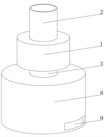
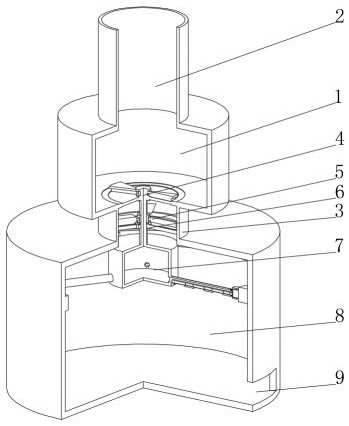
[0042] see Figure 1-3 , the present invention provides a technical solution: an energy-saving sewage treatment equipment, which specifically includes:
[0043] The processing tray 1, the top and bottom central positions of the processing tray 1 are respectively connected with a water inlet pipe 2 and a processing pipe 3, and a filter device 4 is provided on the top of the inner wall of the processing pipe 3;
[0044] Spiral fan 5, the spiral fan 5 is arranged inside the processing tube 3, the outer side of the spiral fan 5 is provided with a fixed casing 6, the outer side of the fixed casing 6 is fixedly connected with the inner wall of the processing tube 3, the top of the spiral fan 5 is connected with the filter device 4 through the rotating shaft, and the screw The bottom of the fan 5 is fixedly connected with a discharging device 7 through the rotating shaft;
[0045] a treatment box 8, the top of the treatment box 8 is communicated with the bottom of the treatment pipe...
Embodiment 2
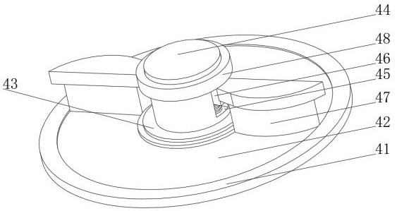
[0056] see Figure 1-4 , on the basis of the first embodiment, the present invention provides a technical solution: the brush head 47 includes a fixing plate 471, the bottom of the fixing plate 471 is fixedly connected with bristles 472, and the side of one end of the bristles 472 away from the fixing plate 471 is fixedly connected with barbs. One side of the plate 471 is set in an arc shape, the distribution of the bristles 472 is adapted to the arc-shaped side of the fixing plate 471, the barbs on the bristles 472 are arranged in multiple groups and are staggered, one end of the fixing plate 471 is fixedly connected with the slider 46, and the bristles are The bottom of 472 extends to the upper surface of the filter screen 42, and is provided with a brush head 47. When the brush head rotates on the upper surface of the filter screen 42, the flocs on the filter screen 42 can be hooked away by the barbs on the bristles 472 to avoid flocculation. The brush head 47 can be guided...
Embodiment 3
[0058] see Figure 1-5 , On the basis of Embodiment 1 and Embodiment 2, the present invention provides a technical solution: the discharging device 7 includes a discharging tray 71, the side of the discharging tray 71 is connected with a discharging pipe 72, and the bottom of the discharging pipe 72 is provided with a discharging pipe 72. The material hole 73, the inner wall of the discharge pipe 72 is slidably connected with a retaining bar 74, the retaining bar 74 is provided with an adapter hole 75, one end of the retaining bar 74 extends to the outside of the discharging pipe 72 and is fixedly connected with a slider 76, the slider 76 is far away from One side of the gear bar 74 is rotatably connected with a roller 77, a return spring is arranged between the slider 76 and the discharging pipe 72, and a side of the roller 77 away from the slider 76 is slidably connected with a fixed ring 78, and the inner wall of the fixed ring 78 is fixedly connected with a fixed ring 78. ...
PUM
 Abstract
Description
Claims
Application Information
 - R&D
- Intellectual Property
- Life Sciences
- Materials
- Tech Scout
- Unparalleled Data Quality
- Higher Quality Content
- 60% Fewer Hallucinations
Browse by: Latest US Patents, China's latest patents, Technical Efficacy Thesaurus, Application Domain, Technology Topic, Popular Technical Reports.
© 2025 PatSnap. All rights reserved.Legal|Privacy policy|Modern Slavery Act Transparency Statement|Sitemap|About US| Contact US: help@patsnap.com


