Nondestructive mixed transportation device for krill

A krill and mixed transportation technology, applied in the field of marine fishery, can solve the problems affecting the integrity of krill, impact and collision of krill, etc., and achieve the effects of reducing extrusion damage, reducing impact force and ensuring integrity

Pending Publication Date: 2022-07-22
OCEANOGRAPHIC INSTR RES INST SHANDONG ACAD OF SCI
View PDF0 Cites 0 Cited by
  • Summary
  • Abstract
  • Description
  • Claims
  • Application Information

AI Technical Summary

Problems solved by technology

However, when the rotational speed of the centrifugal impeller is high, the position of the blade tip and the vortex tongue of the flow channel will impact and collide with the krill, which will affect the integrity of the krill and adversely affect the processing of the krill in the later stage.

Method used


Image

  • Nondestructive mixed transportation device for krill
  • Nondestructive mixed transportation device for krill
  • Nondestructive mixed transportation device for krill

Examples


Embodiment 1

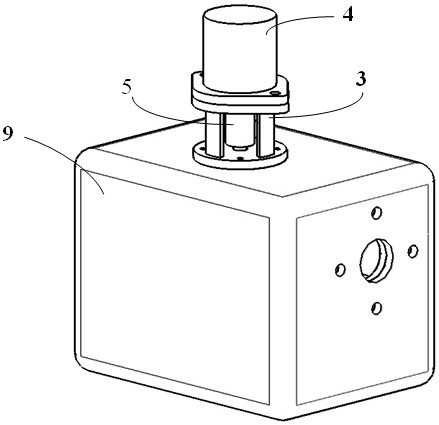
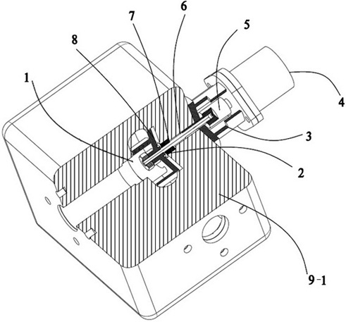
[0033] Embodiment 1 The non-destructive mixing and transporting device for krill provided in this embodiment has an overall structure as follows: figure 1 and 2 As shown, it includes a krill mixing channel 1, a sealing device 2, a motor bracket 3, a motor 4, a coupling 5, a transmission shaft 6, an anti-cavitation impeller 8, a casing 9, and the like.

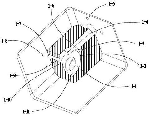
[0034] like figure 2 As shown, in this embodiment, the krill mixing channel 1 is a channel opened inside the solid shell 9-1, and mainly includes an inlet channel 1-1, a main channel 1-11, and an outlet channel 1-4. The inlet flow channel 1-1 and the outlet flow channel 1-4 are in a vertical relationship with the main flow channel 1-11 respectively. As shown in the figure, the main flow channel 1-11 is a hollow structure similar to a volute. The upper end is communicated with the middle of the main channel 1-11, and the inner end of the outlet channel 1-4 is communicated with the outlet of the main channel 1-11, forming a kr...

Embodiment 2

[0046] Embodiment 2 The non-destructive mixing and transporting device for krill provided in this embodiment has an overall structure as follows: figure 1 , 9 As shown in and 10, the structure is basically the same as that of Embodiment 1, including the krill mixing channel, the sealing device 2, the motor bracket 3, the motor 4, the coupling 5, the transmission shaft 6, the anti-cavitation impeller 8, and the casing 9. Wait. The difference is that, in this embodiment, the casing 9 is a hollow casing 9-2, and an end cover 10 is provided above the krill mixing channel.

[0047] The krill mixing channel is a channel arranged inside the hollow shell 9-2, and mainly includes an inlet channel 1-1, a main channel 1-11, and an outlet channel 1-4. The inlet flow channel 1-1 and the outlet flow channel 1-4 are in a spatial vertical relationship with the main flow channel 1-11, such as Figure 10 , 11 As shown, the main flow channel 1-11 is a hollow structure similar to a volute, th...


PUM


Abstract

The invention belongs to the technical field of marine fishery, and particularly relates to a mixed transportation device for krill transportation operation. The lossless krill mixed transportation device comprises a krill mixed transportation flow channel and an anti-cavitation impeller, the krill mixed transportation flow channel comprises an inlet flow channel, a main flow channel and an outlet flow channel which are communicated in sequence; the anti-cavitation impeller is arranged in the main runner; the anti-cavitation impeller is provided with two arc-shaped blades which are spirally arranged in a staggered manner; a micro-channel along the trend of the blade is arranged in the arc-shaped blade; one end of the micro-channel is opened on the outer side wall of the front end of the arc-shaped blade, and the other end of the micro-channel is opened at the tail end of the arc-shaped blade. According to the device, the micro-channels are arranged in the impeller, cavitation of fluid entering the impeller is reduced, meanwhile, the transition device and the buffer damping device are arranged at the front end where the fluid flows from the outlet, the impact force of the fluid in the channels on the krill is further reduced, extrusion damage to the krill is relieved, and the integrity of the krill is guaranteed.

Description

technical field [0001] The invention belongs to the technical field of marine fishery, and in particular relates to a mixing and conveying device used in krill conveying operations. Background technique [0002] With the rapid development of modern marine fishery equipment, high-efficiency Antarctic krill mixed transportation equipment came into being. At this stage, the mixing equipment for krill is mostly centrifugal mixing equipment, which mainly improves the mixing efficiency through centrifugal impellers. However, when the rotational speed of the centrifugal impeller is high, the position of the blade tip and the vortex tongue of the flow channel will impact and collide with the krill, which will affect the integrity of the krill and adversely affect the later processing of the krill. [0003] Based on the above considerations, a flow control structure is introduced to the position where the impact force is relatively large during the krill transportation process to co...

Claims


Application Information

Patent Timeline
Patent Type & Authority Applications(China)
IPC IPC(8): F04D1/00F04D13/06F04D29/42F04D29/22F04D29/24F04D29/66
CPCF04D1/00F04D13/06F04D29/426F04D29/2238F04D29/242F04D29/669
Inventor 郝宗睿赵志范任万龙王越刘刚华志励徐娟
Owner OCEANOGRAPHIC INSTR RES INST SHANDONG ACAD OF SCI
Why Eureka
Try Eureka