Center body of flame tube for radial staged combustion chamber

A technology of center body and flame tube, applied in the field of gas turbine engine, achieves the effect of good cooling effect, high reliability, and satisfying expansion requirements

Pending Publication Date: 2022-07-22
成都中科翼能科技有限公司
View PDF0 Cites 2 Cited by
  • Summary
  • Abstract
  • Description
  • Claims
  • Application Information

AI Technical Summary

Problems solved by technology

[0011] In order to solve the problems of cooling and installation of the central body in the prior art, this solution provides a central body for the flame tube of the radially graded combustion chamber

Method used


Image

  • Center body of flame tube for radial staged combustion chamber
  • Center body of flame tube for radial staged combustion chamber
  • Center body of flame tube for radial staged combustion chamber

Examples


Embodiment 1

[0039]At present, staged combustion technology has been widely used in aero-engines and gas turbine engines. As far as the structure of the combustion chamber formed by staged combustion technology is concerned, it can be divided into axially staged combustion chamber and radially staged combustion chamber. Compared with Below, because the radially staged combustion chamber structure has a more compact structure and a lighter structure, it has a wider application range. In the radially staged combustion chamber, in order to realize the staged and partitioned combustion between the duty flame and the main combustion stage flame, a central body structure is usually set between the duty flame head and the main combustion stage flame head, and produces Isolate the gas film to separate the duty flame and the main combustion stage flame to avoid mutual interference between the two.

[0040] However, the cooling structure of the existing central body is complex, the cooling effect is...

Embodiment 2

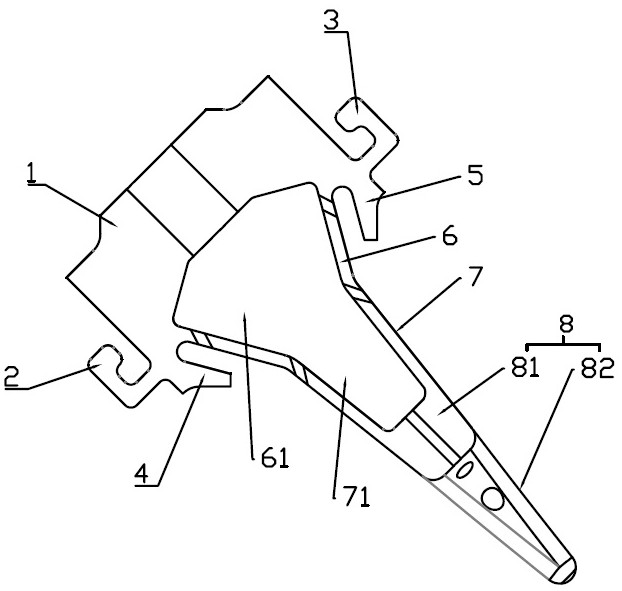
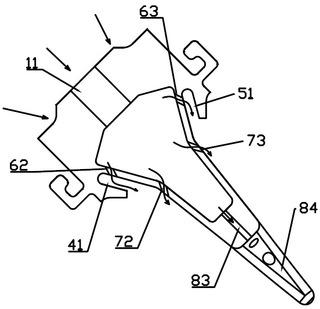
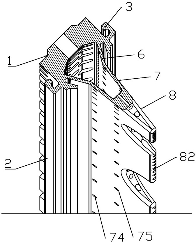
[0043] like Figure 1 to Figure 5 As shown, on the basis of the structure of Embodiment 1, in order to effectively avoid the ablation of the central body and improve the cooling effect of the central body, the cooling structure of this embodiment is designed.

[0044] The mixed flow cavity 61 and the pressure accumulating cavity 71 together form a ring cavity located in the central body. The annular cavity has the effect of annular pressure equalization. The holes lead the air flow in the annular cavity out of the center body, and respectively form cooling air films on the inner ring side and the outer ring side of the center body. The cooling gas film can not only isolate the heat from the main combustion stage flame and the duty stage flame to the central body, but also cool the central body, thereby taking away the heat of the central body.

[0045] The pressure-gathering cavity 71 located in the pressure-gathering section 7 is a part of the ring cavity, and the plurality ...

Embodiment 3

[0053] like Figure 1 to Figure 5 As shown, on the basis of the structure of Embodiment 1 or Embodiment 2, the jet section 8 with several central holes can be divided into a jet front section 81 and a jet rear section 82 along the jet direction, and the jet rear section 82 can be distributed with several The flame grooves 84 and the cross-fire grooves 84 can be semicircular grooves or arc grooves.

[0054] Since the input quantity of the flame head of the main combustion stage is not the same under different working conditions of the gas turbine engine, when switching between different working conditions, the on-duty flame is often required to carry out the operation of the oil and gas mixture ejected from the flame head of the main combustion stage. In the conventional structure, the taper of the jet section 8 and the injection direction of the central hole are changed to ensure the ignition effect; however, this method greatly changes the overall structure of the central bod...


PUM


Abstract

The invention belongs to the technical field of gas turbine engines, and particularly relates to a center body of a flame tube for a radial staged combustion chamber, the center body is annular and can be arranged between a main combustion stage flame head and an on-duty stage flame head, a plurality of air inlet holes are formed in the front side of the center body, and a plurality of air outlet holes are formed in the rear side of the center body. A plurality of center holes are formed in the rear side of the center body; an annular cavity is formed in the center body, and the center hole and the air inlet hole are both communicated with the annular cavity; a plurality of inclined holes are formed in the inner cavity wall and the outer cavity wall of the annular cavity, airflow is led out of the center body, and a cooling air film is formed outside the center body. The center body has the advantages of being simple in structure, convenient to install, high in reliability, long in service life and the like. Mutual independent stable combustion of on-duty level flames and main combustion level flames can be achieved, and cross flame of the on-duty level flames and the main combustion level flames can be achieved when working conditions are switched. The center body can be made of a high-temperature alloy material, so that ablation in a high-temperature working environment for a long time is avoided.

Description

technical field [0001] The invention belongs to the technical field of gas turbine engines, and in particular relates to a center body of a flame tube used for a radially staged combustion chamber. Background technique [0002] Since the end of the last century, the development of advanced gas turbine engines has focused on further improving the performance of each component, expanding the stable working range of the gas turbine engine, reducing the number of components, and improving the reliability, life and thrust-weight ratio of the gas turbine engine. Reduce fuel consumption and pollutant emissions. [0003] In order to solve the above problems, the United States has launched the "Energy Efficient Engine (E3) Program", "High Performance Turbine Engine Technology (IHPTET) Program" and "High Speed ​​Civil Aircraft (HSCT) Program" and other programs. Among them, the goal of the "High Speed ​​Civil Aircraft (HSCT) Plan" is to achieve the NOx emission index of less than 10 ...

Claims


Application Information

Patent Timeline
Patent Type & Authority Applications(China)
IPC IPC(8): F23R3/18F23R3/28
CPCF23R3/18F23R3/286F23R3/283
Inventor 王龙王鸣刘宝琪范珍涔高原陈柳君代茂林王少波王梁丞杨治
Owner 成都中科翼能科技有限公司
Why Eureka
Try Eureka