Laser radar

A laser radar and light source technology, applied in the field of laser detection, can solve the problems of limiting the scanning speed of lidar, expanding the detection distance, and increasing the offset distance, and achieves the effect of breaking through the limitations of scanning speed and detection distance and improving the coupling efficiency.

Pending Publication Date: 2022-07-22
HESAI TECH CO LTD
View PDF0 Cites 4 Cited by
  • Summary
  • Abstract
  • Description
  • Claims
  • Application Information

AI Technical Summary

Problems solved by technology

[0004] As the target distance increases and the laser propagation time prolongs, the delay angle expands and the offset distance increases. Therefore, the delay angle limits the increase in the scanning speed and detection range of the laser radar.

Method used


Image

  • Laser radar
  • Laser radar
  • Laser radar

Examples


Embodiment Construction

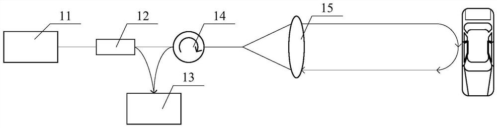
[0038] It can be known from the background art that a laser radar in the prior art has the problem that the scanning speed and the detection distance are limited due to the delay angle. Now combined with the lidar structure and its optical path, the reasons for the limited scanning speed and detection distance are analyzed:

[0039] Lidars that use coherent detection, such as Frequency Modulated Continuous Wave (FMCW) radars, directly mix the echo light reflected by the target with the transmitted signal by transmitting a beam whose frequency changes regularly with time. Since the frequency difference between the two is related to the target distance and relative speed, the target distance and relative speed information can be calculated from the frequency difference.

[0040] The coherent detection principle of FMCW lidar requires that the local oscillator light and the reflected echo have extremely high parallelism, and an angle of 0.1 degrees will generate interference frin...


PUM


Abstract

The laser radar comprises a light source structure, a coaxial transceiving structure comprising a view field adjusting unit and a detection structure which are sequentially arranged along a light path, the center position of the detection structure deviates from the coaxial position corresponding to the light source structure, and the deviation direction and distance of the detection structure are set according to the rotation angular velocity of the view field adjusting unit and the detection distance of the laser radar. According to the technical scheme, the focus point of the echo light formed when the view field adjusting unit rotates corresponds to the center position of the detection structure as much as possible, the coupling efficiency of the detection structure is improved, and then the limitation of the scanning speed and the detection distance is broken through.

Description

technical field [0001] The invention relates to laser detection, in particular to a laser radar. Background technique [0002] Lidar has been widely used in aerospace, military confrontation, remote sensing mapping, meteorology and disaster warning and many other fields, especially in recent years, the performance requirements of vehicle Lidar in the fields of assisted driving and unmanned driving have increased significantly, which has driven Vehicle lidar will further develop in the direction of high resolution, high precision, long detection distance, large field of view, miniaturization and low power consumption. [0003] At present, there is a kind of lidar that realizes the scanning of the outgoing beam by means of continuous rotation. In a laser radar with a common transmission and reception path, the scanning device not only needs to realize the scanning of the outgoing beam, but also needs to realize the collection of the echo beam formed by the reflection of the t...

Claims


Application Information

Patent Timeline
Patent Type & Authority Applications(China)
IPC IPC(8): G01S7/481
CPCG01S7/4817G01S7/4818G01S7/4812
Inventor 潘政清孙恺向少卿
Owner HESAI TECH CO LTD
Why Eureka
Try Eureka