
Groove type alkali polishing and cleaning equipment

A cleaning equipment and trough-type technology, applied in cleaning methods and utensils, cleaning methods using liquids, chemical instruments and methods, etc., can solve problems such as long fixed points, inability to fix, and chip damage, to improve firmness and guarantee. The effect of adsorption stability

Pending Publication Date: 2022-07-22
江苏龙恒新能源有限公司
View PDF1 Cites 0 Cited by
  • Summary
  • Abstract
  • Description
  • Claims
  • Application Information

AI Technical Summary

Problems solved by technology

[0006] This kind of cleaning equipment has the advantage that the wafer is cleaned more thoroughly, and it is convenient to quickly dry the cleaned wafer. However, when this cleaning equipment cleans the wafer, it needs to fix the wafer as a whole in the cleaning tank. The existing fixing structure exists The connection point is hard, and it is easy to damage the chip under the action of washing. At the same time, the position of the fixed point is constant. If the size of the chip is large, the fixed point is close to the middle of the chip, which will easily cause damage to the chip at the edge. There is a problem that the fixed point is far away and cannot be fixed

Method used


Image

  • Groove type alkali polishing and cleaning equipment
  • Groove type alkali polishing and cleaning equipment
  • Groove type alkali polishing and cleaning equipment

Examples


Embodiment Construction

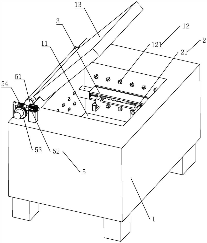
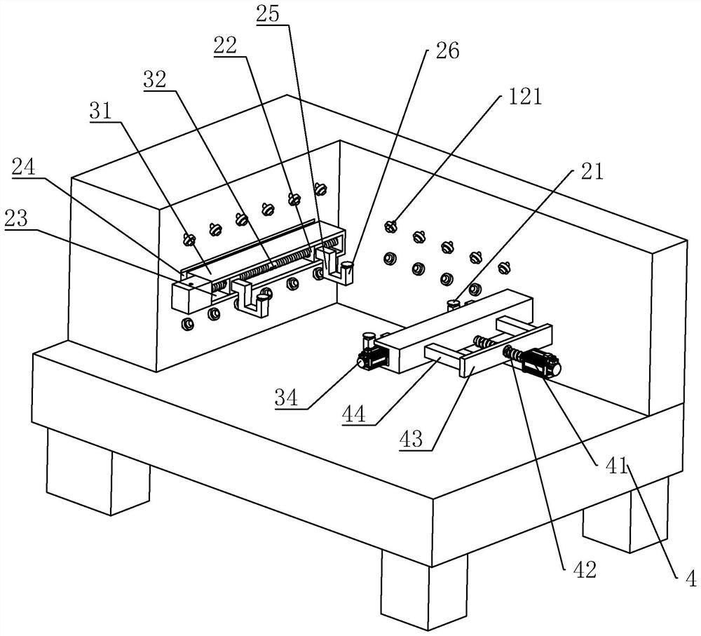
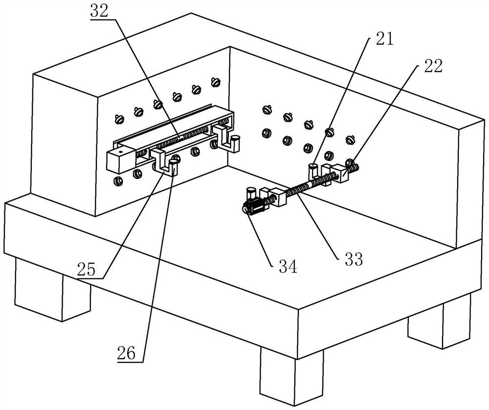
[0027] The present embodiment provides a trough-type alkaline polishing and cleaning equipment, the structure is as follows Figure 1-3 As shown, it includes a body 1, a cleaning tank 11 arranged in the body 1, and a cleaning mechanism 12. The cleaning mechanism 12 includes a number of cleaning heads 121 fixed on the inner sidewall of the cleaning tank 11. The cleaning heads 121 are arranged toward the center of the wafer to clean The heads 121 are provided with two groups, which are respectively fixed at two heights corresponding to the upper and lower sides of the inner side wall of the cleaning tank 11 .

[0028] like Figure 1-3 As shown, the body 1 is provided with a cover plate 13 for closing and opening the cleaning tank 11. The cover plate 13 is rotatably connected to the body 1 through a rotating shaft 51. The size of the cover plate 13 is smaller than that of the cleaning tank 11 to match each other. A rotating member 5 for driving the rotating shaft 51 and the cove...


PUM


Abstract

The invention discloses trough type alkali polishing and cleaning equipment, and relates to the technical field of solar cell production equipment. A clamping mechanism used for clamping and fixing a wafer is arranged in a cleaning groove of the equipment, the clamping mechanism comprises a suction cup used for adsorbing and fixing the wafer, the suction cup is movably connected into the cleaning groove through a fixing base, a movable block is connected to the inner side wall of the cleaning groove in a sliding mode, and the movable block and the fixing base are fixed through a linkage rod. The movable blocks are symmetrically arranged on the two opposite side faces in the cleaning groove, the two movable blocks are symmetrically arranged on each side face, the positions of the fixing bases for fixing the wafers can be adjusted, the overall distance between the fixing bases can be reduced when the sizes of the wafers are small, and the overall distance between the fixing bases can be increased when the sizes of the wafers are large. Therefore, mutual adaptation between the fixed seat and the wafer is realized, the fixed seat is always fixed at the corresponding position of the wafer, the problem that the wafer cannot be fixed or the edge of the wafer is damaged is avoided, and the wafer can be prevented from being damaged by a harder connecting point.

Description

technical field [0001] The invention relates to the technical field of solar cell production equipment, in particular to a trough-type alkali polishing and cleaning equipment. Background technique [0002] The solar cell module is composed of high-efficiency monocrystalline / polycrystalline solar cells, low-iron ultra-white suede tempered glass, packaging materials (EVA, POE, etc.), functional backplane, interconnection bars, bus bars, junction boxes and aluminum alloy frames. . Its service life can reach 15-25 years. [0003] A single solar cell cannot be used as a power source directly. As a power supply, several single cells must be connected in series, connected in parallel and tightly packaged into components. The solar cell module is the core part of the solar power generation system and the most important part of the solar power generation system. [0004] In the production of solar cell modules, polishing and cleaning equipment is required. In order to improve pr...

Claims


Application Information

Patent Timeline
Patent Type & Authority Applications(China)
IPC IPC(8): H01L21/67H01L21/683B08B3/02B08B3/08B08B13/00
CPCH01L21/67051H01L21/6838B08B3/02B08B3/08B08B13/00
Inventor 刘飞顾玉龙桂山刘爱楚
Owner 江苏龙恒新能源有限公司
Learn More