
Stereo scanning laser lamp without slip ring

A three-dimensional scanning and laser light technology, applied in the field of laser light, can solve the problems of corrosion, contact wear resistance, corrosion resistance, relatively high electrical conductivity, life impact, etc., to improve stability and reliability, transmission mode Precise and reliable, reliable connection and transmission effect

Pending Publication Date: 2022-07-26
西安名都光电科技有限公司
View PDF0 Cites 0 Cited by
  • Summary
  • Abstract
  • Description
  • Claims
  • Application Information

AI Technical Summary

Problems solved by technology

[0002] At present, the three-dimensional scanning laser lamp mostly adopts the technical scheme of circular motion and electrical signal transmission using conductive slip rings. An obvious disadvantage of this technology is: because the conductive slip ring adopts the method of sliding contact between the static contact and the moving contact. For the transmission of electrical signals, the requirements for contact wear resistance, corrosion resistance, conductivity, etc. are relatively high, and the cost is also high. Even so, because the slip ring is in a state of motion for a long time, the wear and tear of the dynamic and static contacts is still relatively serious. Failures are also inevitable
Especially in an environment with relatively high humidity, the oxidation and corrosion of the contacts are more serious, and the probability of causing a conductive slip ring failure is also relatively high; The situation of the rail also happens from time to time, which affects the working stability of the conductive slip ring
It also increases the failure of the laser lamp and affects the service life. In view of this, we propose a three-dimensional scanning laser lamp without slip rings

Method used


Image

  • Stereo scanning laser lamp without slip ring
  • Stereo scanning laser lamp without slip ring

Examples


Embodiment

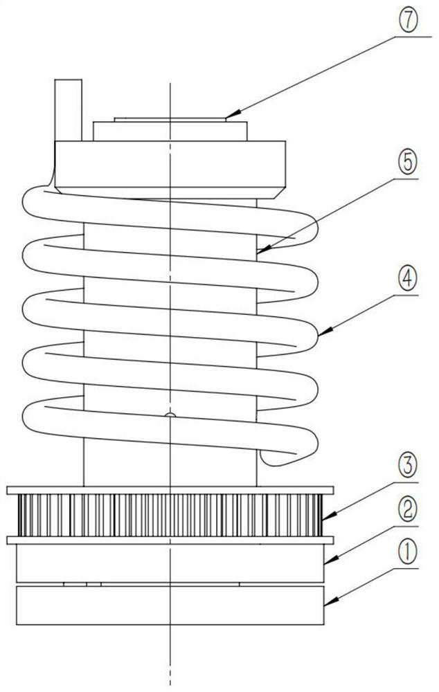
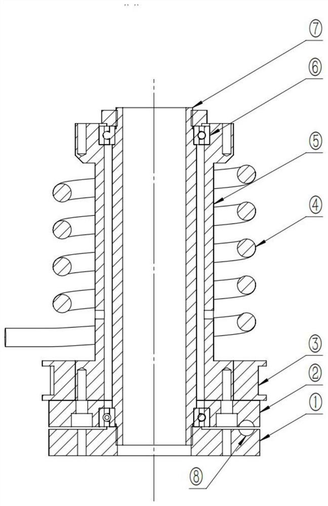
[0027] see Figure 1-2 , a three-dimensional scanning laser light without slip ring, including:

[0028] a light guide tube assembly, the light guide tube assembly is used to provide the optical path and channel of the laser beam;

[0029] Spiral signal transmission assembly, the spiral signal transmission assembly is sleeved on the light guide tube assembly;

[0030] a movement component, which is sleeved on one end of the light guide tube component;

[0031] The spiral signal transmission component is a structure in which the wire is wound into a spiral shape. Its purpose is to provide different requirements for the change of the length of the wire during the movement of the moving component. There are three functions. The third is to prevent the cables from being entangled in the retraction and release of cables of different lengths.

[0032] The positioning component is used to ensure the movement and positioning of the moving component, and the positioning component is...


PUM


Abstract

The invention discloses a slip-ring-free three-dimensional scanning laser lamp, and belongs to the technical field of laser lamps. A slip-ring-free three-dimensional scanning laser lamp comprises a light guide cylinder assembly which is used for providing a light path and a channel of a laser beam; the spiral signal transmission assembly is arranged on the light guide cylinder assembly in a sleeving manner; the movement assembly is arranged at one end of the light guide cylinder assembly in a sleeving manner; the positioning assembly is used for ensuring movement and positioning of the movement assembly, and the positioning assembly is arranged at the bottom of the movement assembly. The spiral signal transmission assembly is used for transmitting electric signals, a contact sliding signal transmission mode of a conductive sliding ring is replaced, non-contact and non-sliding signal transmission is achieved, and the defect of sliding signal transmission is overcome; the system operation stability and reliability are improved, and the service life of the laser lamp can be effectively prolonged.

Description

technical field [0001] The invention relates to the technical field of laser lamps, and more particularly, to a three-dimensional scanning laser lamp without a slip ring. Background technique [0002] At present, the three-dimensional scanning laser lamps mostly use conductive slip rings to realize circular motion and electrical signal transmission. An obvious disadvantage of this technology is that the conductive slip rings use the method of sliding contact between the static contact and the moving contact. The transmission of electrical signals requires relatively high wear resistance, corrosion resistance and electrical conductivity of the contacts, and the cost is also relatively high. That is to say, because the slip ring is in motion for a long time, the wear of the dynamic and static contacts is still relatively serious. Failures are also inevitable. Especially in the environment with relatively high humidity, the contact oxidation and corrosion are more serious, and...

Claims


Application Information

Patent Timeline
Patent Type & Authority Applications(China)
IPC IPC(8): F21S10/00F21V8/00G02B26/10
CPCF21S10/005G02B26/103F21V2200/40
Inventor 孙凯黄轲琴宗明陈永茂
Owner 西安名都光电科技有限公司
Learn More