Manufacturing method for water collecting pipe in vacuum chamber of Tokamak device

A tokamak and manufacturing method technology, applied in the field of magnetic confinement nuclear fusion device manufacturing, can solve the problems that the water collection pipe manufacturing process cannot meet the vacuum airtightness use requirements, etc., to ensure long-term use quality, reduce deformation resistance, and reduce welding Effect of Difficulty and Number of Welds

Pending Publication Date: 2022-07-29
SOUTHWESTERN INST OF PHYSICS
View PDF0 Cites 0 Cited by
  • Summary
  • Abstract
  • Description
  • Claims
  • Application Information

AI Technical Summary

Problems solved by technology

[0010] The purpose of the present invention is to provide a method for manufacturing the water collection pipe in the vacuum chamber of the tokamak device, so as to solve the problem that the existing water collection pipe manufacturing process cannot meet the requirements of vacuum air tightness, relative magnetic permeability and long-term use under high temperature and high pressure Require

Method used


Image

  • Manufacturing method for water collecting pipe in vacuum chamber of Tokamak device
  • Manufacturing method for water collecting pipe in vacuum chamber of Tokamak device
  • Manufacturing method for water collecting pipe in vacuum chamber of Tokamak device

Examples


Embodiment 1

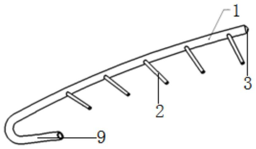
[0051] manufactured as figure 1 The water collecting pipe shown is composed of a main pipe 1. The main pipe 1 has an arc shape with a small curvature. The thickness of the pipe wall of the main pipe 1 is 2mm to 3mm; The thickness is 2mm; one end of the main pipe 1 is welded with a head 3, and the other end of the main pipe 1 is bent at a certain angle in the form of an elbow and has an opening with a large curvature. Manufactured as follows:

[0052] Step 1: Expand the blanking

[0053] First, open the main pipe 1 and branch pipe 2 of the water collection pipe, and use stainless steel pipes to cut the main pipe 1 and branch pipe 2 respectively. Control the wall thickness of the main pipe 1 raw material to be 1mm larger than the minimum required wall thickness of the finished product to compensate for the bending and pulling of the main pipe 1. Pull out the thinning of the flange. The raw material of the stainless steel pipe is qualified for non-destructive testing and the m...

Embodiment 2

[0074] manufactured as figure 1 The water collecting pipe shown is composed of a main pipe 1. The main pipe 1 has an arc shape with a small curvature. The thickness of the pipe wall of the main pipe 1 is 2mm to 3mm; The thickness is 2mm; one end of the main pipe 1 is welded with a head 3, and the other end of the main pipe 1 is bent at a certain angle in the form of an elbow and has an opening with a large curvature. Manufactured as follows:

[0075] The contents of Steps 1 and 2 are consistent with those of Embodiment 1.

[0076] Step 3: Process the main pipe and draw the bottom hole

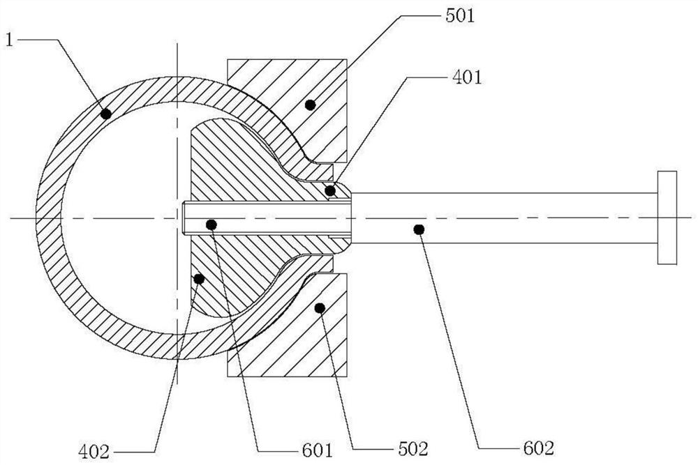
[0077] The bottom hole before the drawing process is processed at the position of the branch pipe 2 on the main pipe 1, and the diameter of the drawing bottom hole is 6 mm smaller than the inner diameter of the branch pipe 2.

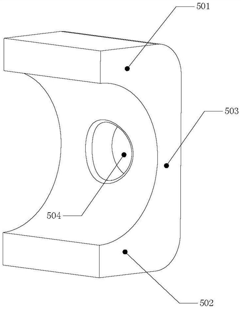
[0078] Step 4: Pull the flange of branch pipe 2 of main pipe 1

[0079] Use a drawing die to pull out the flange of the branch pipe 2 of the main pipe 1. During dra...


PUM

PropertyMeasurementUnit
Thicknessaaaaaaaaaa
Wall thicknessaaaaaaaaaa

Abstract

The invention discloses a method for manufacturing a water collecting pipe in a vacuum chamber of a Tokamak device. The method comprises the following steps: respectively blanking a main pipe and a branch pipe of the water collecting pipe; a bottom hole is machined in the position of the branch pipe on the main pipe; a branch pipe flange of the main pipe is drawn out at each bottom hole, the pipe drawing area of the main pipe is heated to 900-1150 DEG C during drawing, and the length of the outer surface of the drawn branch pipe flange is larger than or equal to 3 mm; welding grooves in the welding positions of the main pipe, the branch pipe and the end socket are machined respectively; welding the branch pipes and the end sockets; the thickness of the pipe wall of the main pipe is 2-3 mm, and the thickness of the wall of the branch pipe is 2 mm. The branch pipe flanges are drawn on the main pipe, so that the welding difficulty of the branch pipes and the number of welding seams are reduced, the welding seams can be subjected to radiographic inspection, and the vacuum airtightness and the long-term use quality of the water collecting pipe are guaranteed; and the deformation resistance of drawing is reduced by high-temperature drawing, so that the relative permeability can be stably kept to be less than 1.04.

Description

technical field [0001] The invention relates to the technical field of manufacturing magnetic confinement nuclear fusion devices, in particular to a manufacturing method for a water collecting pipe in a vacuum chamber of a tokamak device. Background technique [0002] In order to develop new energy in the future, various developed countries are actively carrying out magnetic confinement nuclear fusion research with tokamak as the main way. In tokamak devices, the wall material facing the plasma is generally referred to as the first wall. During the operation of the plasma experiment, the surface of the first wall material will directly face the bombardment of the plasma boundary particles, and the surface temperature of the first wall material will reach thousands of degrees Celsius. The first wall member and the divertor module are cooled. Since there are as many as dozens to hundreds of groups of first wall parts in a vacuum chamber and the cooling water circuit of the d...

Claims


Application Information

Patent Timeline
IPC IPC(8): B23P15/00
CPCB23P15/00Y02E30/10
Inventor 蔡立君侯吉来卢勇刘雨祥李云峰张龙刘健赖春林刘宽程黄文玉宋斌斌唐乐
Owner SOUTHWESTERN INST OF PHYSICS
Why Eureka
Try Eureka