Stray light correction method of optical remote sensing camera

An optical remote sensing and correction method technology, applied in the field of aerospace remote sensing, can solve the problems of overcorrection of stray light and overestimation of the real signal in the imaging area, and achieve the effect of reducing technical requirements, simple and reliable method, strong versatility and practicability

Pending Publication Date: 2022-07-29
HEFEI INSTITUTES OF PHYSICAL SCIENCE - CHINESE ACAD OF SCI
View PDF0 Cites 0 Cited by
  • Summary
  • Abstract
  • Description
  • Claims
  • Application Information

AI Technical Summary

Problems solved by technology

However, the stray light distribution matrix is ​​measured in a darkroom environment in the laboratory. Under real scene imaging conditions, the stray light response obtained by multiplying the stray light distribution matrix tested in the laboratory by the image response of real scene imaging will have a negative impact on imaging. The problem of overestimation of the real signal in the area leads to overcorrection of stray light

Method used


Image

  • Stray light correction method of optical remote sensing camera
  • Stray light correction method of optical remote sensing camera
  • Stray light correction method of optical remote sensing camera

Examples


Embodiment 1

[0044] The focal length is 5.54mm, the field of view is 119°, and the optical remote sensing camera mounted on a certain type of satellite with a working band range of 443-910nm performs stray light correction.

[0045] The specific steps of this embodiment are as follows, such as figure 2 shown:

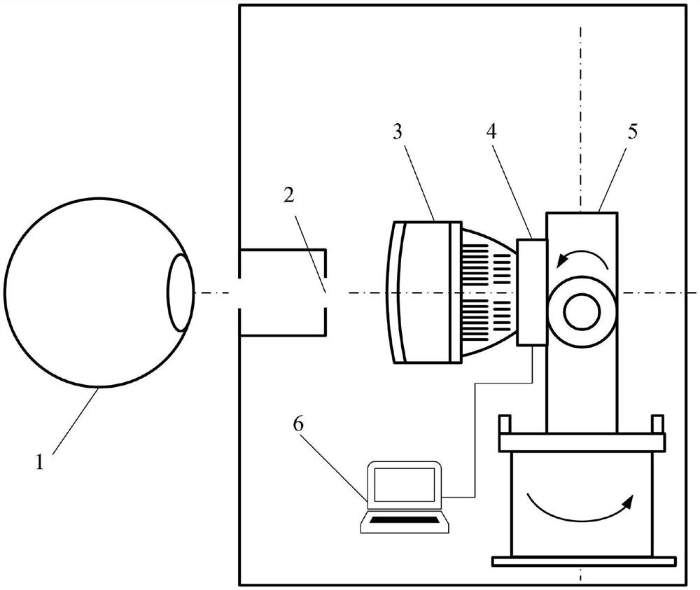
[0046] Step 1. Build a stray light test system, such as figure 1 shown:

[0047] The stray light test system is composed of an integrating sphere light source 1, a field diaphragm 2, an optical remote sensing camera, a two-dimensional turntable 5 and a computer 6. The optical remote sensing camera includes a lens 3, a photodetector 4 and is in a dark room environment; the two-dimensional turntable 5 An optical remote sensing camera is installed on it;

[0048] In a dark room environment, an integrating sphere light source 1, a field diaphragm 2, and an optical remote sensing camera are sequentially arranged, and the centers of the integrating sphere light source 1 and the field ...

Embodiment 2

[0072] The focal length is 4.8mm, the field of view is 107°, and the optical remote sensing camera mounted on a certain type of satellite with a working band range of 490-910nm performs stray light correction.

[0073] The concrete steps of this embodiment are as follows:

[0074] Step 1. Build a stray light test system, which is consistent with Step 1 in Example 1.

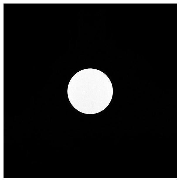
[0075] Step 2. In this embodiment, the imaging target surface is divided into 11×7 illumination areas. Follow the ray trace to determine the corresponding field stop size for each illuminated area. Set the short integration time of each illumination area to 20ms, so that the signal value of each illumination area is not saturated, so that 100 non-saturated images of each illumination area are captured by the optical remote sensing camera; then set the long integration time of each illumination area 1500ms to saturate the signal value of each illumination area, so that 100 saturated images of each illumination a...


PUM


Abstract

The invention discloses a stray light correction method for an optical remote sensing camera, and the method comprises the steps: 1, building a test system, carrying out the regional illumination of an image plane of the camera, and obtaining an image of each region through a focal plane detector array; 2, preprocessing the image; 3, calculating a stray light influence factor of the illumination area of each image to each pixel in other non-illumination areas, setting the stray light influence factor of the imaging area to be zero, and forming a stray light distribution matrix of each area image by the stray light influence factors of all pixels; and 4, shooting an image by the camera in a real scene, keeping the image partition consistent with the step 1, calculating the stray light influence of each region, and deducting the sum of the stray light influence of each region from the original measurement image by adopting an iterative optimization correction algorithm to complete stray light correction. The stray light correction method for the optical remote sensing camera can realize stray light correction of the optical remote sensing camera, is simple and reliable, has relatively high universality and transportability, and provides guarantee for accurate remote sensing data application.

Description

technical field [0001] The invention belongs to the technical field of aerospace remote sensing, in particular to a method for correcting stray light of an optical remote sensing camera. Background technique [0002] Stray light is light that reaches the detector along the path of non-imaging light rays, creating stray light radiant energy that reduces the contrast and clarity of the image. In some serious cases, the target image is even buried in the stray light radiation, which seriously affects the quantitative application of remote sensing data. Most optical remote sensing cameras at home and abroad are easily affected by stray light and are interfered by stray light from direct sunlight, which limits the level of quantitative application. Therefore, in order to realize the application of high-precision remote sensing data, it is urgent to study how to suppress and eliminate stray light. [0003] Usually, the methods of stray light suppression mainly include: using mat...

Claims


Application Information

Patent Timeline
Patent Type & Authority Applications(China)
IPC IPC(8): G01M11/02G01M11/04G06T5/00
CPCG01M11/02G01M11/04G06T5/007
Inventor 韩琳向光峰孟炳寰孙亮洪津
Owner HEFEI INSTITUTES OF PHYSICAL SCIENCE - CHINESE ACAD OF SCI
Why Eureka
Try Eureka