Supercharge Your Innovation With Domain-Expert AI Agents!

Space laser communication scanning equipment with optical fiber quick-scanning and micro-motion functions

A technology of scanning equipment and laser communication, which is applied in optics, optical components, instruments, etc., can solve the problems of large size of optical machine, high power consumption, and huge system, and achieve the goals of reducing the weight of optical machine, low power consumption, and improving resolution Effect

Pending Publication Date: 2022-07-29
蓝星光域(上海)航天科技有限公司
View PDF0 Cites 0 Cited by
  • Summary
  • Abstract
  • Description
  • Claims
  • Application Information

AI Technical Summary

Problems solved by technology

[0004] The purpose of the present invention is to propose a space for optical fiber fast-scan and micro-motion in view of the existing coarse tracking actuator and fast mirror complex scanning system in the background technology, which are huge, the size of the optical machine is large, and the power consumption is relatively large. Laser communication scanning equipment

Method used


Image

  • Space laser communication scanning equipment with optical fiber quick-scanning and micro-motion functions
  • Space laser communication scanning equipment with optical fiber quick-scanning and micro-motion functions
  • Space laser communication scanning equipment with optical fiber quick-scanning and micro-motion functions

Examples


Embodiment

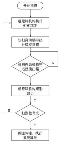
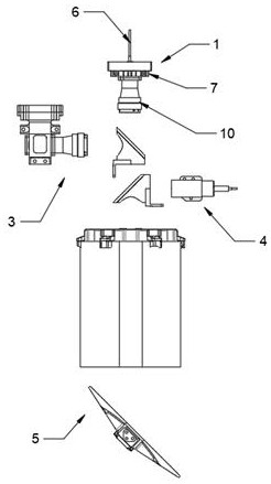
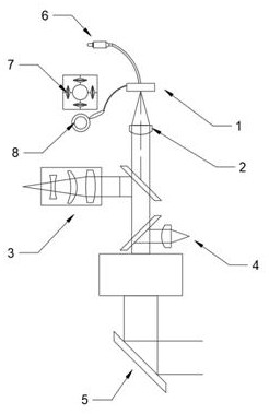
[0030] like figure 1 , figure 2 , image 3 and Figure 5 As shown, an optical fiber fast-scanning micro-movement space laser communication scanning device proposed by the present invention includes a scanning device, and the scanning device includes a composition optical path, and the composition optical path includes a signal transmitting component 2, a tracking camera 3, a signal receiving component 4 and a rough The tracking actuator 5 and the signal emission component 2 include a fast-scan micro-movement actuator 1, an emission fiber 6 and a lens 10. The fast-scan micro-motion actuator 1 is a scanning actuator, and the fast-scan micro-motion actuator 1 performs helical scanning, such as Figure 4 As shown in the figure, the fast-scan micro-actuator 1 is used to control the translation on the launch focal plane 9 of the launch fiber 6, for scanning the signal light to scan the area of ​​the uncertain region 11, and the rough tracking actuator 5 executes the scanning step...


PUM


Abstract

The invention relates to the technical field of communication scanning equipment, in particular to space laser communication scanning equipment with optical fiber quick-scanning and micro-motion functions. Mainly aiming at the problems of large power consumption caused by large system size and large optical machine size of the existing coarse tracking execution mechanism and fast reflecting mirror composite scanning, the invention provides the following technical scheme: the system comprises scanning equipment, and the scanning equipment comprises a light path, the composition light path comprises a signal transmitting assembly, a tracking camera, a signal receiving assembly and a coarse tracking executing mechanism, and the signal transmitting assembly comprises a quick-scanning micro-motion executing mechanism, a transmitting optical fiber and a lens. The transmitting optical fiber translates on a focal plane, and transmits signal light for spiral scanning, so that the scanning process and the light path design are optimized, the number of reflectors is reduced, the transmitting efficiency is improved, the high resolution is realized, the scanning precision is improved, the scanning missing rate is reduced, the weight and the size of an optical machine are reduced, and the power consumption is further reduced. The system is mainly applied to a space laser communication scanning system for optical fiber quick-scanning and micro-motion.

Description

technical field [0001] The invention relates to the technical field of communication scanning equipment, in particular to a space laser communication scanning equipment with optical fiber fast scanning and micro-movement. Background technique [0002] Laser communication technology is the key technology to realize the mutual transmission of big data in space. It is a modern communication technology with high speed, convenience, safety and flexible networking. With the development of science and technology, human space activities have gradually increased, satellite-satellite and satellite-ground. The amount of communication data between them is increasing year by year, and the required coverage is getting wider and wider. A large amount of scientific data needs to rely on large-capacity, high-speed, long-distance spatial information transmission technology to achieve. At present, the volume and weight of most laser communication terminals It is relatively large and the launch...

Claims


Application Information

Patent Timeline
Patent Type & Authority Applications(China)
IPC IPC(8): G02B26/10H04B10/50H04B10/60
CPCG02B26/103H04B10/503H04B10/60
Inventor 郭永志
Owner 蓝星光域(上海)航天科技有限公司
Features
  • R&D
  • Intellectual Property
  • Life Sciences
  • Materials
  • Tech Scout
  • Unparalleled Data Quality
  • Higher Quality Content
  • 60% Fewer Hallucinations
Learn More