Supercharge Your Innovation With Domain-Expert AI Agents!

Method for surface shape reconstruction and directional diagram acquisition of double-reflector antenna

A dual-reflector, antenna surface technology, applied in antennas, geometric CAD, design optimization/simulation, etc., can solve problems such as gain reduction, widening lobe width, and antenna pattern beam shift

Pending Publication Date: 2022-07-29
NO 54 INST OF CHINA ELECTRONICS SCI & TECH GRP
View PDF0 Cites 0 Cited by
  • Summary
  • Abstract
  • Description
  • Claims
  • Application Information

AI Technical Summary

Problems solved by technology

During the actual working process of the antenna, due to the influence of gravity, temperature, wind load, sunlight and other environmental factors, the accuracy of the main surface, the position of the secondary surface, and the position of the feed horn will be further deteriorated
Finally, it will further affect the electrical performance of the antenna, resulting in the beam shift of the antenna pattern, the widening of the lobe width, the increase of the side lobe level, and the decrease of the gain

Method used


Image

  • Method for surface shape reconstruction and directional diagram acquisition of double-reflector antenna
  • Method for surface shape reconstruction and directional diagram acquisition of double-reflector antenna
  • Method for surface shape reconstruction and directional diagram acquisition of double-reflector antenna

Examples


Embodiment Construction

[0061] The present invention will be further described in detail below with reference to the accompanying drawings and specific embodiments.

[0062] A method for obtaining a pattern of a double reflector antenna. The method firstly reconstructs the surface shape of the double reflector antenna to obtain the surface shape reconstruction expression of the main reflector, and then obtains the pattern. The method includes the following steps:

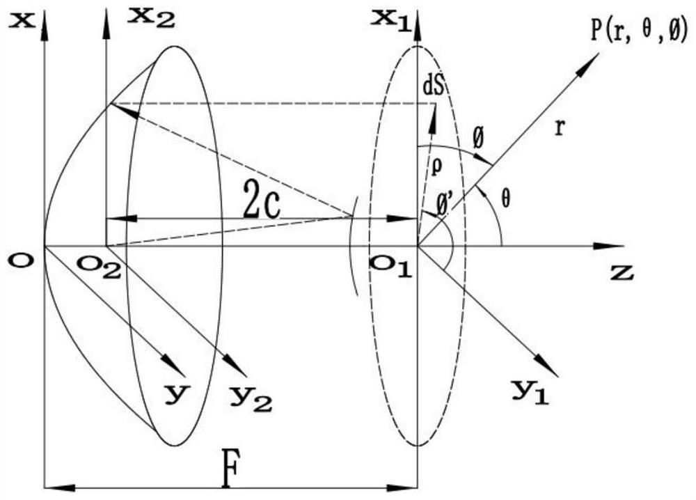
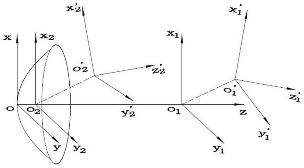
[0063] 1) Taking the standard Cassegrain dual-reflector antenna as an example, it is assumed that the theoretical main surface coordinate system of the dual-reflector antenna is oxyz, and the theoretical main surface coordinate system moves the main surface focal length F along the z-axis to obtain the theoretical secondary surface coordinates Department o 1 x 1 y 1 z 1 , the theoretical subsurface coordinate system is along z 1 Move the hypoid focal length 2c in the negative direction to get the theoretical feed coordinate system o ...


PUM


Abstract

The invention discloses a method for reconstructing the surface shape of a double-reflector antenna and acquiring a directional diagram, and belongs to the technical field of antenna measurement. The method comprises the following steps: calculating deformation deviation values of two main reflecting surfaces; based on a 37-order Zernike polynomial, obtaining a Zernike fitting coefficient vector; combining the two groups of coefficient vectors and Zernike polynomials to obtain deformation reconstruction basic data of the main reflecting surface; a Zernike coefficient vector and a Zernike polynomial are used for describing the wavefront optical path difference of the main reflecting surface, and the deformation phase difference and phase influence factors of the two main reflecting surfaces are obtained; calculating a phase influence factor under feed source position deviation and a feed source directional diagram function under feed source angle deviation; and calculating an ideal antenna far-field pattern, a far-field pattern when the two main reflecting surfaces deform, and a far-field pattern under feed source position deviation, and obtaining basic data of a final far-field pattern of the antenna. According to the method, the influence of antenna structure deformation on the electrical performance is comprehensively considered, and the precision of drawing the antenna far-field pattern is improved.

Description

technical field [0001] The invention relates to the technical field of antenna measurement, in particular to a method for reconstructing the surface shape of a double-reflector antenna and obtaining a pattern. Background technique [0002] With the continuous development of radio communication technology, reflector antennas, as the mainstream equipment in the current communication field, are widely used in satellite communication, radar, remote sensing, radio astronomy and other fields in microwave, millimeter wave, and submillimeter wave bands. In recent years, research on astronomical observation and terahertz communication has become very popular. Dual-reflector antennas have many excellent characteristics in the field of large-diameter and high-frequency communication, and dual-reflector antennas have developed rapidly. Beijing Miyun 50-meter radio telescope, Shanghai 65-meter Tianma radio telescope, Guizhou 500-meter radio telescope, and the largest radio astronomy proj...

Claims


Application Information

Patent Timeline
Patent Type & Authority Applications(China)
IPC IPC(8): G06F30/23G06F30/10H01Q15/14H01Q19/10G06F111/10
CPCG06F30/23G06F30/10H01Q15/14H01Q19/10G06F2111/10
Inventor 孙伟程志峰郝会乾王铮夏立曹江涛王卓伦
Owner NO 54 INST OF CHINA ELECTRONICS SCI & TECH GRP
Features
  • R&D
  • Intellectual Property
  • Life Sciences
  • Materials
  • Tech Scout
  • Unparalleled Data Quality
  • Higher Quality Content
  • 60% Fewer Hallucinations
Learn More