
Divided-flow type sludge and sewage treatment system and treatment process

A sewage treatment system and split-flow technology, applied in water/sludge/sewage treatment, sludge treatment, water/sewage multi-stage treatment, etc. problems, to achieve the effect of improving the filter press effect, improving the practicability, and improving the practicability

Pending Publication Date: 2022-08-02
王树
View PDF0 Cites 1 Cited by
  • Summary
  • Abstract
  • Description
  • Claims
  • Application Information

AI Technical Summary

Problems solved by technology

[0003] Existing sludge dewatering machinery includes vacuum filters, plate and frame filter presses, belt filter presses and centrifuges. Because the belt filter press has the advantages of simple structure, easy operation, stable operation and low cost, it makes The belt filter press has become the main type of sludge dewatering in my country; however, when the filter press roller of the belt filter press filters the sludge, the sludge layer on the filter belt is squeezed by the filter press roller. Squeeze to both sides of the filter belt, resulting in mud running, which will cause the sludge to overflow from both sides of the filter belt, reducing the filtering effect of the filter belt on the sludge, and thus causing the limitations of the existing belt filter press
[0004] In view of this, the present invention proposes a split flow sludge sewage treatment system and treatment process, which solves the problem of sludge overflowing from both sides of the filter belt

Method used


Image

  • Divided-flow type sludge and sewage treatment system and treatment process
  • Divided-flow type sludge and sewage treatment system and treatment process
  • Divided-flow type sludge and sewage treatment system and treatment process

Examples


Embodiment Construction

[0046] In order to make it easy to understand the technical means, creation features, achieved goals and effects of the present invention, the present invention will be further described below with reference to the specific embodiments.

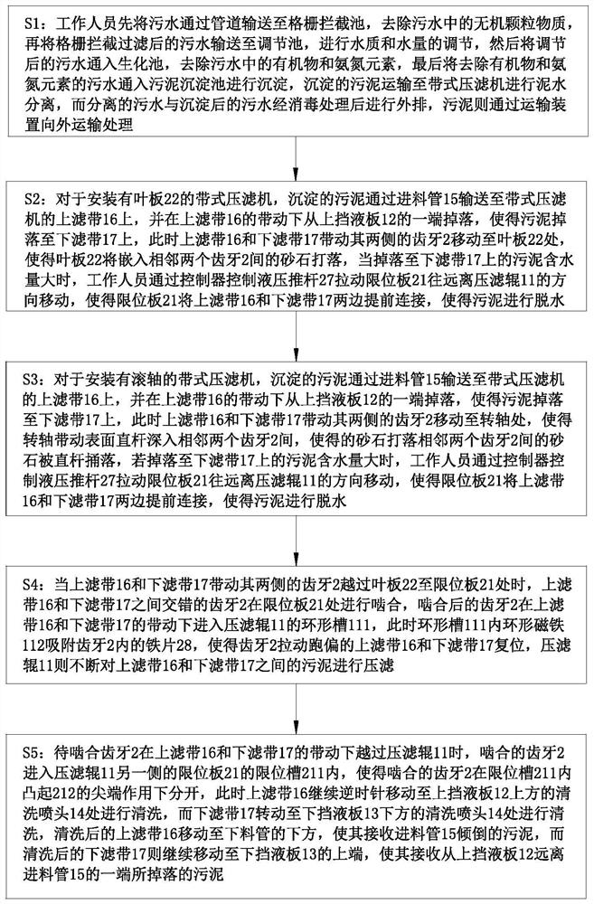
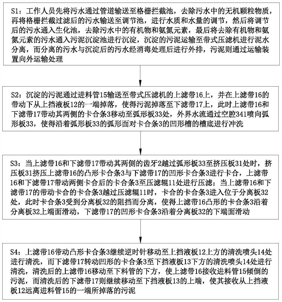
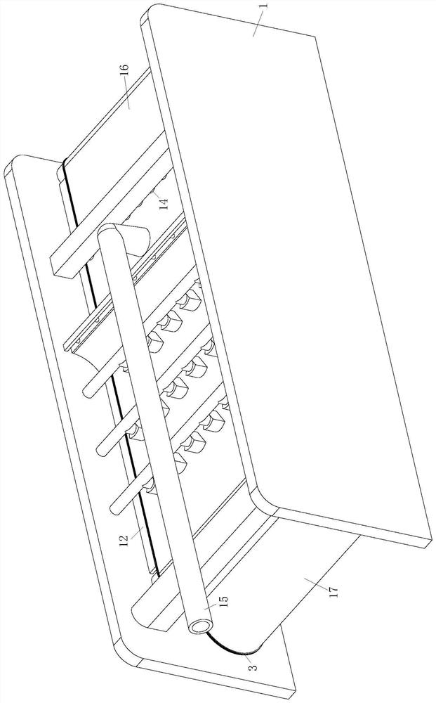
[0047] like Figure 1 to Figure 8 As shown, a split-flow sludge sewage treatment system according to the present invention includes a belt filter press; the belt filter press includes:

[0048] Frame 1, a filter press roller 11 is rotatably installed on the frame 1; an upper liquid baffle 12 is arranged above the filter press roller 11; a lower liquid baffle 13 is arranged below the filter press roller 11; the Both the upper liquid baffle 12 and the lower liquid baffle 13 are fixedly connected to the frame 1; above the upper liquid baffle 12 and below the lower liquid baffle 13 are installed cleaning nozzles 14; the cleaning nozzles 14 are fixedly installed on the On the frame 1; a feeding pipe 15 is installed above the upper liquid baffle 1...


PUM


Abstract

The invention belongs to the technical field of sludge and sewage treatment, and particularly relates to a flow dividing type sludge and sewage treatment system and process. The belt filter press comprises a rack, and a filter pressing roller is rotationally mounted on the rack; an upper liquid baffle is arranged above the filter pressing roller; a lower liquid baffle is arranged below the filter pressing roller; the upper liquid baffle and the lower liquid baffle are fixedly connected with the rack; cleaning nozzles are mounted above the upper liquid baffle and below the lower liquid baffle; through the arrangement of the sealing mechanism, the two sides of the upper filter belt and the lower filter belt are in sealed contact by the sealing mechanism at the positions, close to the filter pressing roller, of the upper filter belt and the lower filter belt, so that the upper filter belt and the lower filter belt are extruded by the filter pressing roller; sludge layers which are located between the upper filter belt and the lower filter belt and are extruded by the filter pressing rollers to flow to the two sides cannot overflow from the two sides of the upper filter belt and the lower filter belt under blocking of the sealing modules, so that the filter pressing effect of the filter belts on the sludge is improved, and the practicability of the device is improved.

Description

technical field [0001] The invention belongs to the technical field of sludge sewage treatment, and in particular relates to a split-flow sludge sewage treatment system and a treatment process. Background technique [0002] Since the pollution and damage to the downstream water bodies caused by urban drainage is related to the drainage system, in order to better protect the environment, the general new drainage system should consider the use of a split system. The way of collecting, transporting and disposing of sewage of different natures by one or more channel systems is usually to set up two sets of pipeline systems to discharge and dispose of rainwater and sewage respectively; After simple treatment, it is discharged into the natural water body. After the sewage is collected, it is transported by pipeline to the sewage treatment plant for centralized treatment, and then discharged after treatment. Because the sewage contains a large amount of sludge, the sewage treatment...

Claims


Application Information

Patent Timeline
Patent Type & Authority Applications(China)
IPC IPC(8): B01D33/04B01D33/48C02F11/123C02F9/14C02F101/16C02F101/30
CPCB01D33/04B01D33/48C02F11/123C02F9/00C02F3/00C02F1/001C02F2001/007C02F2101/30C02F2101/16C02F2303/04
Inventor 王树颜子浩章恒
Owner 王树
Learn More