Efficient automatic spraying equipment
A technology of automatic spraying and equipment, applied in the direction of coating, spray booth, spraying device, etc., can solve the problems of reducing work efficiency, inability to process, paint mixing, etc., to shorten the processing time, improve work efficiency, and improve spray quality Effect
- Summary
- Abstract
- Description
- Claims
- Application Information
AI Technical Summary
Problems solved by technology
Method used
Image
Examples
Embodiment 1
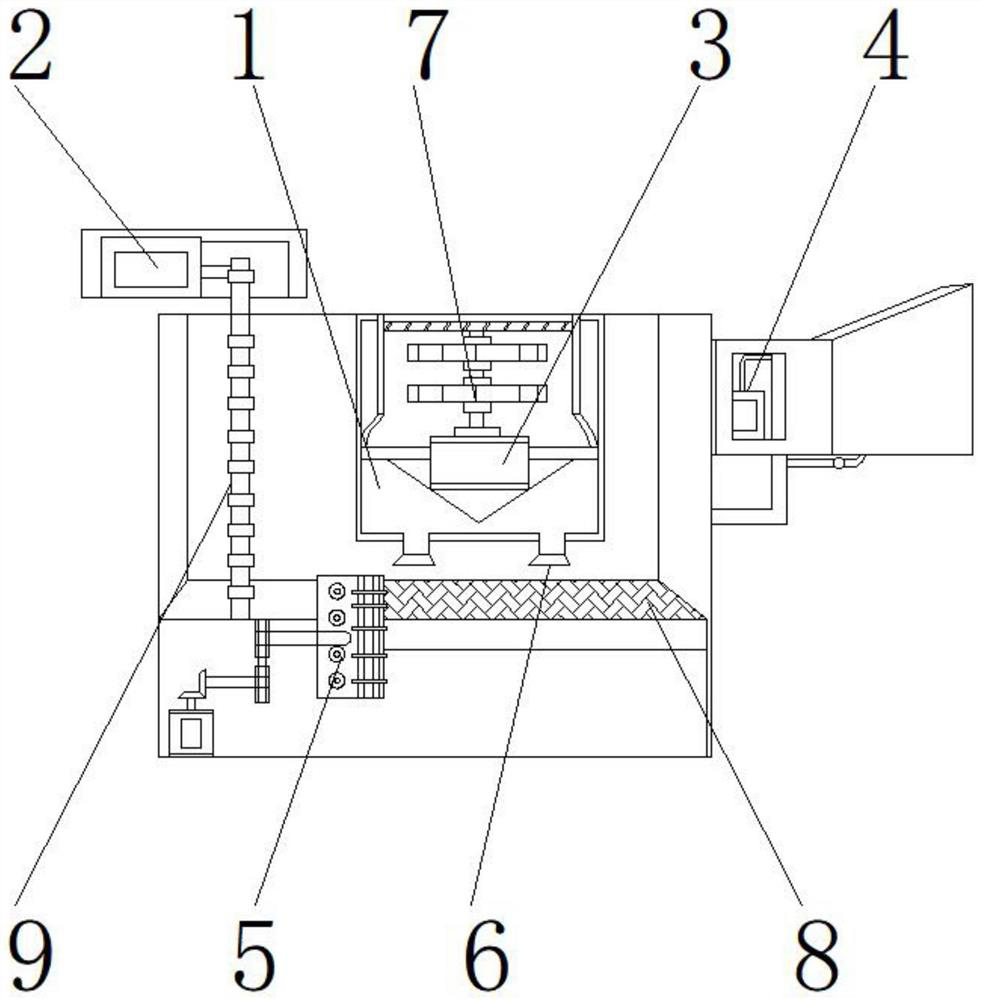
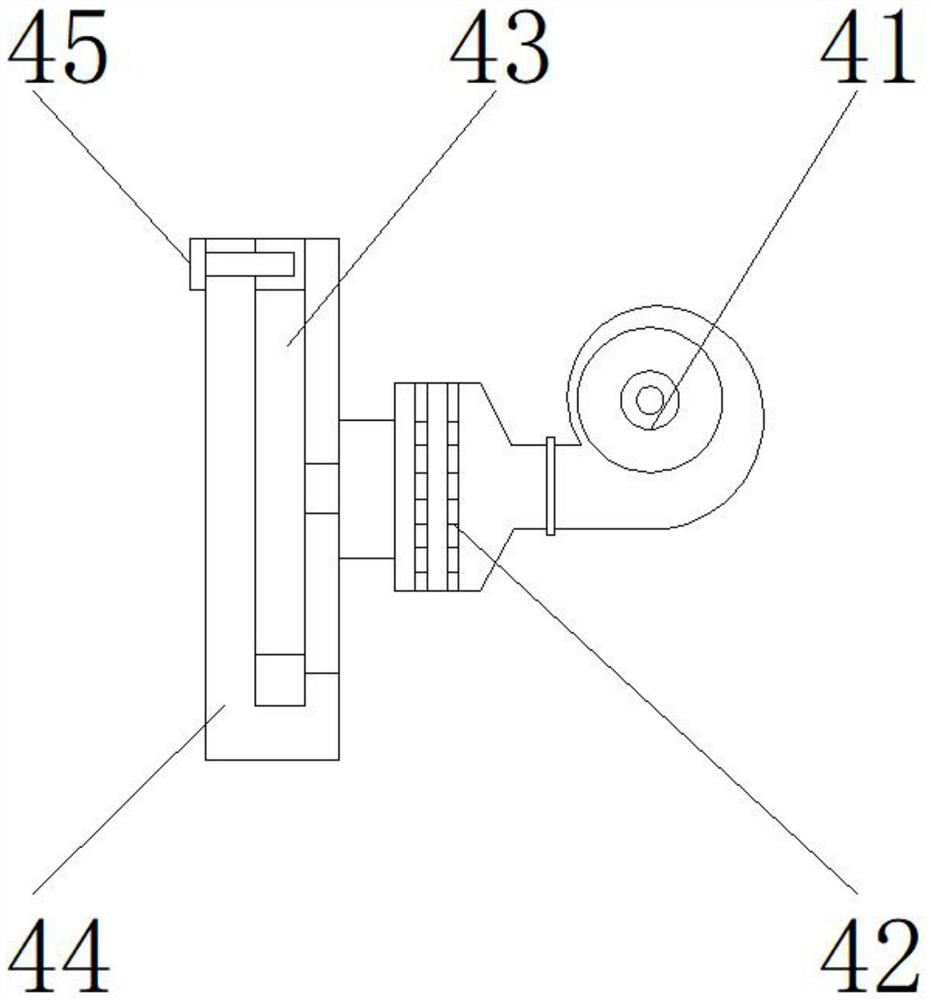
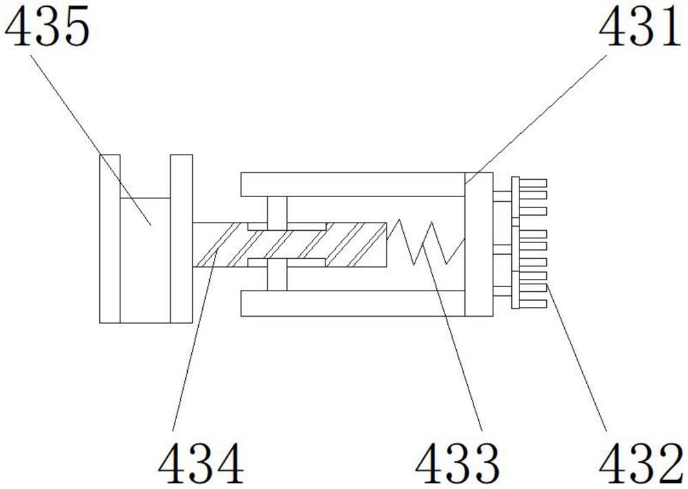
[0025] like Figure 1-5 As shown, the present invention provides a high-efficiency automatic spraying equipment, comprising a main body 1, the upper end of the main body 1 is provided with a clamping seat 3, the upper end of the clamping seat 3 is provided with a spraying range adjusting device 7, and the lower end of the main body 1 is provided with a spray head 6. A worktable 8 is provided below the spray head 6, a drying device 5 is provided on one side of the worktable 8, a guide rod 9 is provided on one side of the main body 1, and a driving device 2 is provided on the upper end of the guide rod 9. The other side is provided with a dust removal device 4; the dust removal device 4 includes a fan 41, a dust collector 42, a blowing dust cleaning device 43, an air collecting hood 44, and an air intake duct 45. Inside the cover 44, the air intake duct 45 is located on the upper end side of the air-collecting and dust-collecting hood 44; a connection hole is provided between th...
Embodiment 2
[0028] like Figure 1-5 As shown, on the basis of Embodiment 1, the present invention provides a technical solution: preferably, the device 7 for adjusting the spraying range includes a motor 71, a rotating shaft 72, an adjusting rod 73, a telescopic spring 74, and a movable shaft 75, and the rotating shaft 72 is located in the motor 71, the adjustment rod 73 is located at the upper end of the rotating shaft 72, the telescopic spring 74 is located at the upper end of the adjustment rod 73, the telescopic movable shaft 75 is located on both sides of the rotating shaft 72, and a movable groove is provided between the rotating shaft 72 and the movable shaft 75, and the One side is movably connected with the lower end of the movable shaft 75 through the movable groove, a welding block is arranged between the rotating shaft 72 and the adjusting rod 73, the upper end of the rotating shaft 72 is fixedly connected with the lower end of the adjusting rod 73 through the welding block, an...
Embodiment 3
[0031] like Figure 1-5 As shown, on the basis of Embodiment 1, the present invention provides a technical solution: preferably, the drying device 5 includes a mounting plate 51, a turbo blower 52, a heater 53, an air inlet duct 54, an air jet head 55, and a turbo blower 52 is located at the lower end of the mounting plate 51, the heater 53 is located on one side of the turbo blower 52, the air inlet pipe 54 is located at the lower end of the heater 53, the jet head 55 is located at the lower end of the air inlet pipe 54, between the mounting plate 51 and the turbo blower 52 Bolts are provided, the lower end of the mounting plate 51 is fixedly connected with the upper end of the turbo blower 52 through the bolts, a conduit is provided between the turbo blower 52 and the heater 53, and one side of the turbo blower 52 is fixedly connected to one side of the heater 53 through the conduit , a notch is provided between the air inlet pipe 54 and the heater 53, the upper end of the a...
PUM
 Abstract
Description
Claims
Application Information
 - R&D
- Intellectual Property
- Life Sciences
- Materials
- Tech Scout
- Unparalleled Data Quality
- Higher Quality Content
- 60% Fewer Hallucinations
Browse by: Latest US Patents, China's latest patents, Technical Efficacy Thesaurus, Application Domain, Technology Topic, Popular Technical Reports.
© 2025 PatSnap. All rights reserved.Legal|Privacy policy|Modern Slavery Act Transparency Statement|Sitemap|About US| Contact US: help@patsnap.com


