High-speed stable linear rail plate 3D printer based on UM structural design

A 3D printer and structural design technology, which is applied to 3D object support structures, coating devices, metal processing equipment, etc. The effect of seat positioning, improving printing speed and improving printing quality

Pending Publication Date: 2022-08-02
LUOYANG INST OF SCI & TECH
View PDF0 Cites 0 Cited by
  • Summary
  • Abstract
  • Description
  • Claims
  • Application Information

AI Technical Summary

Problems solved by technology

[0003] Traditional UM-structured 3D printers only use a linear optical axis for driving and printing, and have very high requirements for the straightness of the optical axis. Often, the cross nozzle jumps when the XY plane moves due to the low linearity of the optical axis, which affects the printing quality and speed. Traditional UM printers often use the form of a screw and an optical axis to move the hot bed platform because of the Z-axis. The installation of the screw is difficult, and it is prone to problems such as non-concentric rotation of the screw, which will also affect the straightness of the Z-axis movement.
[0004] The traditional UM structure 3D printer does not have a belt tightening mechanism for each axis. The user needs to tighten the belt when reassembling the machine. The operation is very cumbersome, and the belt loosening and tightening process in the later stage is very troublesome.
[0005] The traditional UM structure 3D printer cross nozzle uses a bearing copper sleeve to replace the optical axis bearing. Although the volume is reduced, the bearing copper sleeve wears seriously during long-term use, and because the inner surface of the copper sleeve is in surface contact with the optical axis, the frictional resistance is large, and it is easy to Heat generation, also due to the unstable connection of the traditional cross print head, the flatness of the print head is not high when moving, which affects the printing quality and speed

Method used


Image

  • High-speed stable linear rail plate 3D printer based on UM structural design
  • High-speed stable linear rail plate 3D printer based on UM structural design
  • High-speed stable linear rail plate 3D printer based on UM structural design

Examples


Embodiment 1

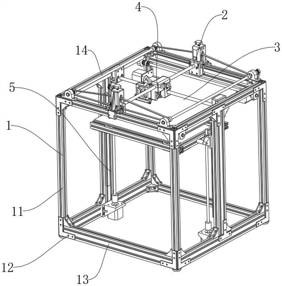
[0050] like Figure 1-Figure 8 As shown, a high-speed and stable linear rail version 3D printer based on UM structure design includes an external support mechanism 1 for external support, a nozzle mechanism 4 for printing raw materials, and an X movement for adjusting the position of the nozzle mechanism 4 Mechanism 2, Y moving mechanism 3, X moving mechanism 2 is installed on the upper end of the outer support mechanism 1, Y moving mechanism 3 is connected to the lower end of the X moving mechanism 2, and a nozzle mechanism 4 is installed between the X moving mechanism 2 and the Y moving mechanism 3. A Z moving mechanism 5 is arranged on the lower side of the mechanism 4;

[0051] The external support mechanism 1 includes a column 11, an L connecting block 12, a cross bar 13, and a vertical bar 14. The vertical column 11, the horizontal bar 13, and the vertical bar 14 are connected by the L connecting block 12 to form a cubic frame;

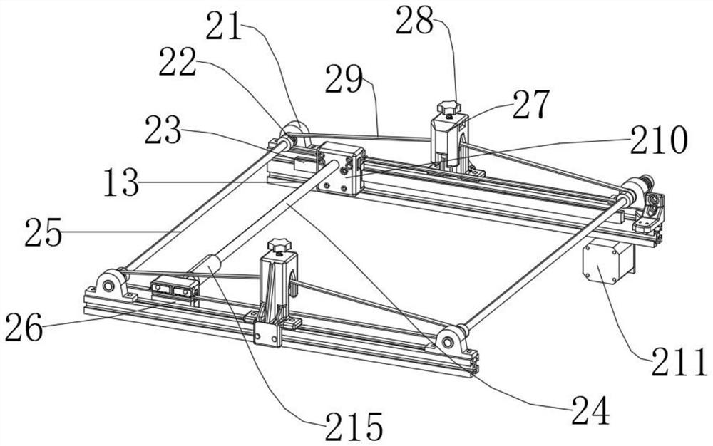
[0052] The X moving mechanism 2 includes...


PUM


Abstract

The invention discloses a high-speed stable linear rail plate 3D printer based on UM structural design, which comprises an outer support mechanism for external support, a spray head mechanism for spraying raw materials for printing, and an X moving mechanism and a Y moving mechanism for adjusting the position of the spray head mechanism, the X moving mechanism is mounted at the upper end of the outer support mechanism, and the Y moving mechanism is mounted at the lower end of the outer support mechanism. The lower end of the X moving mechanism is connected with the Y moving mechanism, the spray head mechanism is installed between the X moving mechanism and the Y moving mechanism, and the Z moving mechanism is arranged on the lower side of the spray head mechanism. The high straightness of the X-direction linear guide rail and the Y-direction linear guide rail is used for guaranteeing the planeness and the repeated positioning precision when the spray head moves, the requirement for the straightness of the linear optical axis is not high, and the problem of transmission pain points of the optical axis of a traditional UM structure is solved.

Description

technical field [0001] The invention relates to the field of 3D printers, in particular to a high-speed and stable line rail version 3D printer based on UM structure design. Background technique [0002] 3D printer, also known as 3D Printer (3DP for short), is a process of Rapid Prototyping (RP), which uses layer by layer to produce 3D models. Its operation process is similar to that of traditional printers. However, traditional printers print ink onto paper to form two-dimensional plane drawings, while three-dimensional printers use liquid photosensitive resin materials, molten plastic filaments, gypsum powder and other materials to achieve layer by layer by spraying adhesive or extrusion. Stacked up to form a three-dimensional solid. [0003] The traditional UM-structured 3D printer only uses a linear optical axis for driving and printing, and has very high requirements on the straightness of the optical axis. Often, the cross nozzle jumps when the XY plane moves due to t...

Claims


Application Information

Patent Timeline
Patent Type & Authority Applications(China)
IPC IPC(8): B29C64/20B29C64/232B29C64/236B29C64/209B33Y30/00
CPCB29C64/20B29C64/232B29C64/236B29C64/209B33Y30/00
Inventor 朱德荣庞乾辰刘博刘选基秦坤鹏吕永奥张卫东王梦阳
Owner LUOYANG INST OF SCI & TECH
Why Eureka
Try Eureka