Full-automatic wire arranging machine for handmade carpet
A fully automatic, wire-arranging machine technology, which is applied in the direction of textiles, papermaking, and braided fabrics, can solve problems such as low work efficiency, error-prone, and difficulty in cooperating with wires and hooks, so as to reduce labor intensity, save production costs, and realize The effect of automation
- Summary
- Abstract
- Description
- Claims
- Application Information
AI Technical Summary
Problems solved by technology
Method used
Image
Examples
Embodiment 1
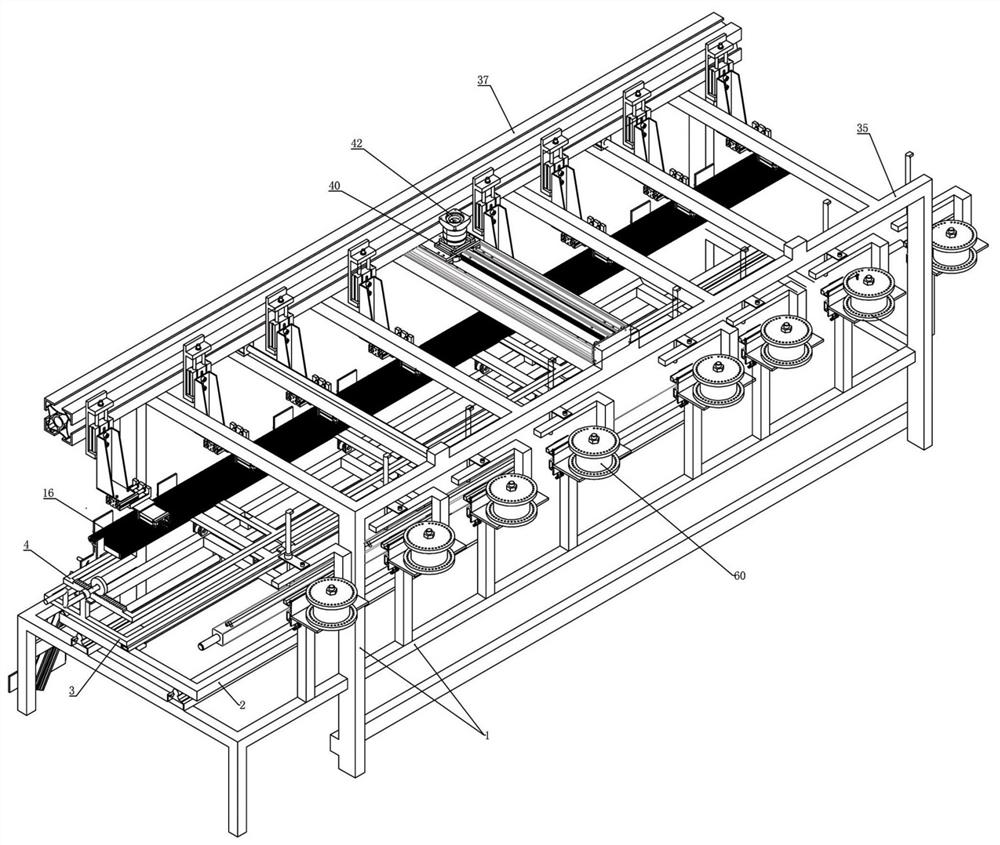
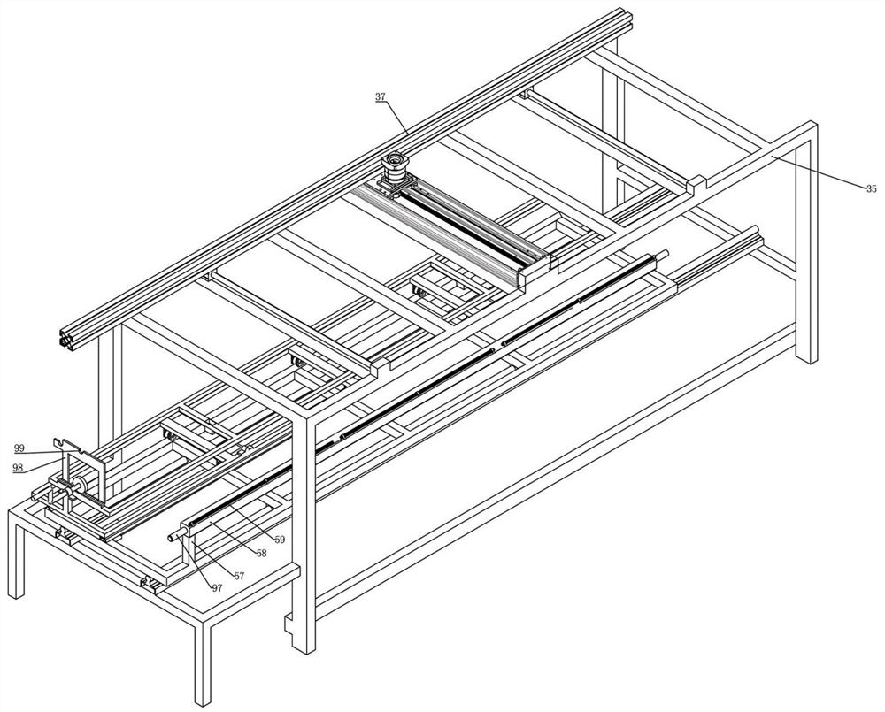
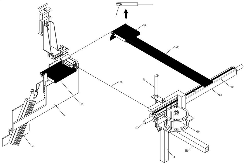
[0048] Example 1: a figure 1 The fully automatic arranging machine for handmade carpets shown is designed to solve the problems of low work efficiency and error-prone problems in the current manual arranging of handmade carpets. figure 2 It can be seen that the frame part of the cable arranging machine mainly includes a bottom movable frame assembly and a top movable frame assembly. In addition, the cable arranging machine also includes a grating precise positioning mechanism, an automatic on-line device and an automatic wire-breaker device for the end of the wire.
[0049] figure 2 , Figure 4 and Figure 7 It can be seen that the bottom movable frame assembly includes a floor frame 1, a high-precision longitudinal transfer frame 2 and a needle plate frame in sequence from bottom to top (the needle plate frame can be a single type or a composite type, as in the subsequent embodiments) , a longitudinal sliding mechanism is set between the landing frame 1 and the high-prec...
Embodiment 2
[0058] Embodiment 2: On the basis of embodiment 1, adopt a kind such as Figure 4 The grating positioning mechanism shown, the grating positioning mechanism is matched with the wire arranging machine, so that the grating positioning mechanism and the needle plate can move synchronously, and the precise positioning function of the grating is used to determine the control of the precise movement of the needle plate.
[0059] Figure 4 Among them, there are a high-precision vertical transfer frame 2 and a needle plate frame in sequence on the floor frame 1. In the process of realizing the high-precision vertical transfer of the needle plate by the equipment, the needle plate frame and the high-precision vertical transfer frame 2 need to be fixed as one. Therefore, the needle plate 16 located on the upper side of the needle plate frame can also be controlled by the controller together with the high-precision vertical moving frame 2 to gradually move vertically according to the gra...
Embodiment 3
[0065] Embodiment 3: On the basis of embodiment 2, as Figure 4 and Figure 7 As shown, a needle plate frame is installed on the upper side of the high-precision vertical transfer frame 2 . In this embodiment, the needle plate frame is a composite needle plate frame, including a needle plate base frame 3 and a needle plate adjustment frame 4 .
[0066] The needle plate 16 is fixed on the needle plate frame, specifically the needle plate adjusting frame 4 . The needle plate 16 is a combination of a series of single plates evenly spaced, or a plate body equivalent to a grating plate (that is, including a main body plate and a plurality of independent single plate bodies), and a series of single plates are fixed on the After the top of the needle plate holder, there is a fitting gap between the adjacent single-piece plates.
[0067] A longitudinal rail is fixed on the upper side of the high-precision vertical transfer frame 2, and the needle board base frame 3 is mounted on the...
PUM
 Abstract
Description
Claims
Application Information
 - R&D
- Intellectual Property
- Life Sciences
- Materials
- Tech Scout
- Unparalleled Data Quality
- Higher Quality Content
- 60% Fewer Hallucinations
Browse by: Latest US Patents, China's latest patents, Technical Efficacy Thesaurus, Application Domain, Technology Topic, Popular Technical Reports.
© 2025 PatSnap. All rights reserved.Legal|Privacy policy|Modern Slavery Act Transparency Statement|Sitemap|About US| Contact US: help@patsnap.com


