Efficient coloring equipment for fabric textile processing
A high-efficiency, high-quality fabric technology, applied in the processing of textile materials, equipment configuration, textiles and papermaking, textile materials processing, etc., can solve problems such as insufficient coloring, poor adaptability, and reduced performance, so as to achieve uniform coloring and improve work efficiency. Efficiency and usability, the effect of reducing limitations
- Summary
- Abstract
- Description
- Claims
- Application Information
AI Technical Summary
Problems solved by technology
Method used
Image
Examples
Embodiment 1
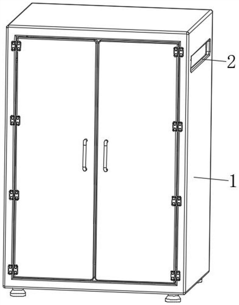
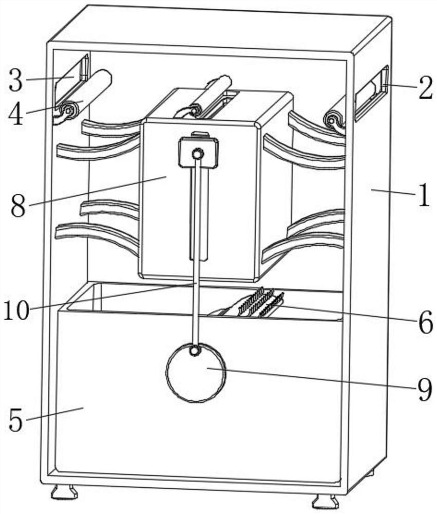
[0028] see Figure 1-Figure 7 , the present invention provides a technical solution: a high-efficiency coloring equipment for fabric textile processing, comprising a body 1, a feed port 2 is opened on one side of the top surface of the body 1, and the top of the surface of the body 1 is far from the feed port 2. A discharge port 3 is opened on one side, and guide rollers 4 are arranged inside the body 1 and near the feed port 2 and the discharge port 3. The central position of the bottom of the inner wall of the body 1 is fixedly connected with a dyeing tank 5. The dyeing tank 5 A toggle device 6 is provided on the inner wall of the inner wall and near the central position. Both ends of the toggle device 6 penetrate through the inner wall of the dyeing tank 5 and extend to the outside. The bottom side of the surface of the body 1 is provided with a power mechanism 7. The output end is fixedly connected with one end of the toggle device 6 through a coupling, a residual material...
Embodiment 2
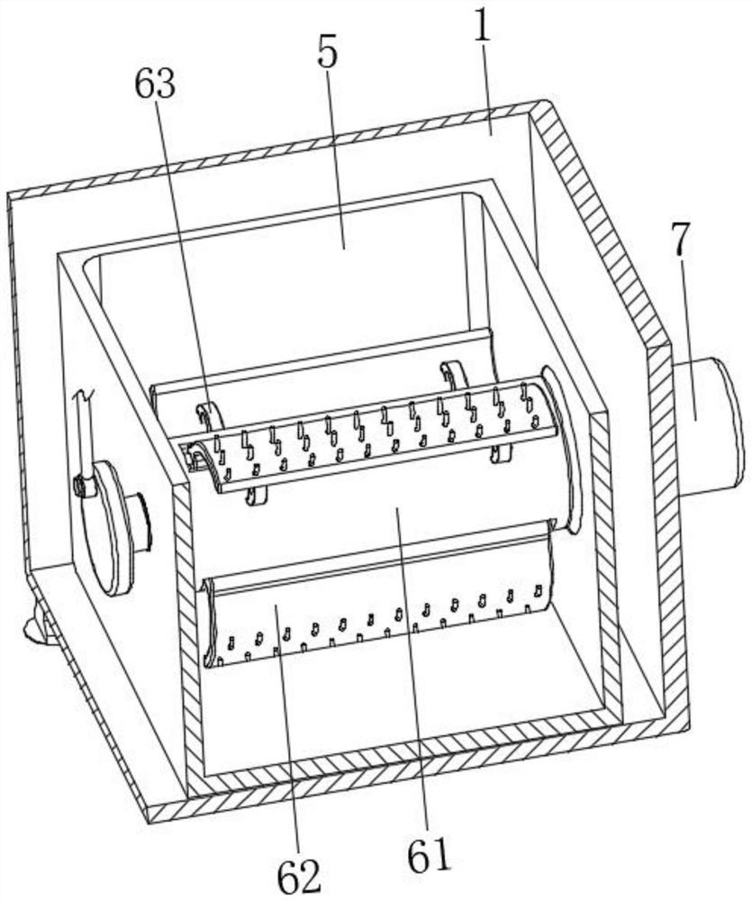
[0030] The toggle device 6 includes a driving roller body 61, the end of the driving roller body 61 is rotatably connected with the inner wall of the dyeing tank 5, the surface side of the turntable 9 is fixedly connected with one end of the driving roller body 61, and the output end of the power mechanism 7 is connected through the coupling. The shaft is fixedly connected with one end of the driving roller body 61, the surface of the driving roller body 61 is provided with a reverse carding device 62, and the edge of the surface of the reverse carding device 62 is fixedly connected with the two sides corresponding to the surface of the driving roller body 61. Elasticity Support 63 .
[0031] The reverse carding device 62 is evenly distributed on the surface of the driving roller body 61, and the elastic supports 63 are evenly distributed between the surface edge of the reverse carding device 62 and the two sides corresponding to the surface of the driving roller body 61. When ...
Embodiment 3
[0035] The residual material processing device 8 includes a casing 81, the surface of the casing 81 is fixedly connected to the inner wall of the body 1 through a bracket, and a sliding block 82 is slidably connected to the surface end of the casing 81, and the surface of the sliding block 82 is connected to the connecting rod 10. The top and bottom of the casing 81 are connected in rotation, the top and bottom of the casing 81 are provided with through holes 83, the top and bottom of the casing 81 and the positions close to the through holes 83 are provided with support rollers 84, and the interior of the casing 81 is provided with cleaning A device 85, the end of the cleaning device 85 is fixedly connected to the surface of the slider 82.
[0036] The cleaning device 85 includes a cover 851, the end of the cover 851 is fixedly connected with the surface of the slider 82, a rectangular gap 852 is opened at the top center of the cover 851, and a support rod 853 is fixedly conne...
PUM
 Abstract
Description
Claims
Application Information
 - R&D
- Intellectual Property
- Life Sciences
- Materials
- Tech Scout
- Unparalleled Data Quality
- Higher Quality Content
- 60% Fewer Hallucinations
Browse by: Latest US Patents, China's latest patents, Technical Efficacy Thesaurus, Application Domain, Technology Topic, Popular Technical Reports.
© 2025 PatSnap. All rights reserved.Legal|Privacy policy|Modern Slavery Act Transparency Statement|Sitemap|About US| Contact US: help@patsnap.com


