
Circuit path level NBTI aging prediction method and device based on key gate

A circuit path and aging prediction technology, which is applied in the circuit field, can solve the problems that the prediction accuracy and speed are difficult to guarantee at the same time, and achieve the effect of reducing training complexity, meeting the prediction accuracy and speed, and reducing the amount of model calculation

Pending Publication Date: 2022-08-02
ANHUI UNIV OF SCI & TECH
View PDF0 Cites 0 Cited by
  • Summary
  • Abstract
  • Description
  • Claims
  • Application Information

AI Technical Summary

Problems solved by technology

[0008] The technical problem to be solved by the present invention lies in the problem that the prediction accuracy and speed of the existing method of predicting the aging delay of the critical path are difficult to guarantee at the same time

Method used


Image

  • Circuit path level NBTI aging prediction method and device based on key gate
  • Circuit path level NBTI aging prediction method and device based on key gate
  • Circuit path level NBTI aging prediction method and device based on key gate

Examples


Embodiment 1

[0058] A circuit-path-level NBTI aging prediction method based on critical gates, the method includes:

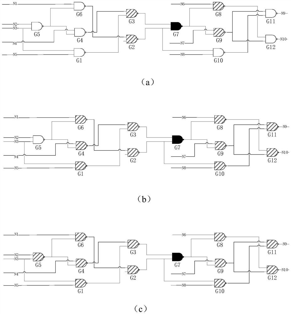
[0059] S1. Obtain key sub-circuits, such as figure 1 As shown, the steps to obtain key subcircuits include:

[0060] A directed graph representation of the circuit is expressed as G=(V, E), V={v i ,1≤i≤n} as a set of nodes, representing the gates in the circuit; E={e j ,1≤j≤m} as a set of edges, representing the connection between gates; first establish the initial set TO i , the v i Join TO i , then the v i The predecessor node and successor node join the set TO i and set TO1 i , TO1 i called v i A layer of topology ring, then TO1 i The predecessor and successor nodes of each node in , and these nodes are not included in TO1 i , adding TO i and TO2 i , TO2 i called v i Layer 2 topology ring, and so on, TO3 i called v i The three-layer topological ring of the final obtained TO i That is, the three-layer ring sub-circuit. Find each node v in the circuit by...

Embodiment 2

[0105] Based on Embodiment 1, Embodiment 2 of the present invention further provides a circuit-path-level NBTI aging prediction apparatus based on critical gates, and the apparatus includes:

[0106] Dataset building blocks for building training and test sets;

[0107] The training module is used to train the linear regression model using the training set. During the training process, the input of the model is the aging delay data of the 0th and 1st years of the key subcircuit, and the output of the model is the second year of the key subcircuit. The aging delay data to the Nth year, N is a positive integer greater than 2;

[0108] The verification module is used to verify the trained linear regression model using the test set after the training is completed. During the verification process, the input of the model is the aging delay data of the 0th and 1st years of the critical path, and the output of the model is the key The aging delay data of the trail from year 2 to year ...


PUM


Abstract

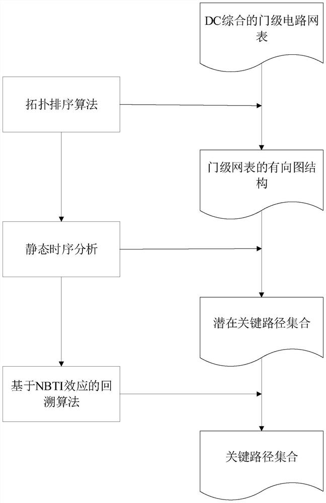
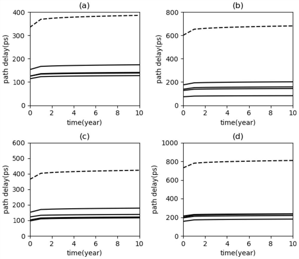
The invention discloses a circuit path level NBTI aging prediction method and device based on a key gate. The method comprises the following steps: constructing a training set and a test set; the training set is used for training a linear regression model, in the training process, the input of the model is aging delay data of the 0th year and the 1st year of the key sub-circuit, the output of the model is aging delay data of the key sub-circuit from the 2nd year to the Nth year, and N is a positive integer larger than 2; after training is completed, a test set is used for verifying the trained linear regression model, in the verification process, input of the model is aging delay data of the zero year and the first year of the key path, and output of the model is aging delay data of the key path from the second year to the Nth year of the key path; after the test is completed, inputting the aging delay data of the 0-th year and the first year of the key path to be predicted into the final linear regression model, and predicting the aging delay data of the second year to the Nth year; the method has the advantage that the prediction precision and speed are guaranteed at the same time.

Description

technical field [0001] The present invention relates to the technical field of circuits, and more particularly to a method and device for predicting the aging of circuit path-level NBTI based on key gates. Background technique [0002] As the size of the CMOS process continues to shrink, the performance of the circuit continues to improve, and the characteristics of the transistors have also undergone great changes, which brings great challenges to the reliability of the circuit. Negative bias temperature instability (NBTI) and hot carrier injection (HCI) are the main causes of circuit aging. They will affect the electrical characteristics of transistors and lead to circuit timing disorder, even cause circuit failure. Among these aging effects, the NBTI effect is considered to be the most important factor. The NBTI effect mainly acts on the PMOS tube. When the PMOS tube is in a negative bias state, that is, V gs =-V dd , the transistor is under pressure at this time. Wit...

Claims


Application Information

Patent Timeline
Patent Type & Authority Applications(China)
IPC IPC(8): G06F30/30G06F30/27G06K9/62G06N20/00G06F119/04
CPCG06F30/30G06F30/27G06N20/00G06F2119/04G06F18/214Y04S10/50
Inventor 孙侠朱瑞徐辉马瑞君朱烁方贤进宁亚飞刘璇
Owner ANHUI UNIV OF SCI & TECH
Learn More