
Visual servo method based on image error weighted vector

A weighted vector and visual servoing technology, applied in the field of robot visual servoing, can solve the problems of huge time and computing power overhead, difficulty in ensuring the quality of control points, and difficulty in guaranteeing the quality of feature points. The effect of small control errors

Pending Publication Date: 2022-08-02
ZHEJIANG UNIV
View PDF0 Cites 0 Cited by
  • Summary
  • Abstract
  • Description
  • Claims
  • Application Information

AI Technical Summary

Problems solved by technology

[0003] The current hardware and algorithms already support the real-time extraction of image feature points, but selecting appropriate feature points from thousands of feature points, using the method of brute force traversal will lead to huge time and computing power overhead, and random selection of control points Because the method does not define a reasonable feature point screening mechanism, it is difficult to guarantee the quality of the randomly obtained control points. Often it is necessary to try repeatedly or increase the number of control points to obtain a set of control points that can be used.
In addition, in the process of visual servoing, if the previously selected control points are mis-matched, tracking fails or exceeds the boundary of the image, the image-based visual servoing algorithm will fail, which will inevitably lead to the failure of the visual servoing task. However, the currently commonly used method of randomly reselecting control points also has the problem that it is difficult to guarantee the quality of feature points.

Method used


Image

  • Visual servo method based on image error weighted vector
  • Visual servo method based on image error weighted vector
  • Visual servo method based on image error weighted vector

Examples


Embodiment Construction

[0034] Embodiments of the present invention are described in detail below. The embodiments described below with reference to the accompanying drawings are exemplary, and are intended to explain the present invention and should not be construed as limiting the present invention.

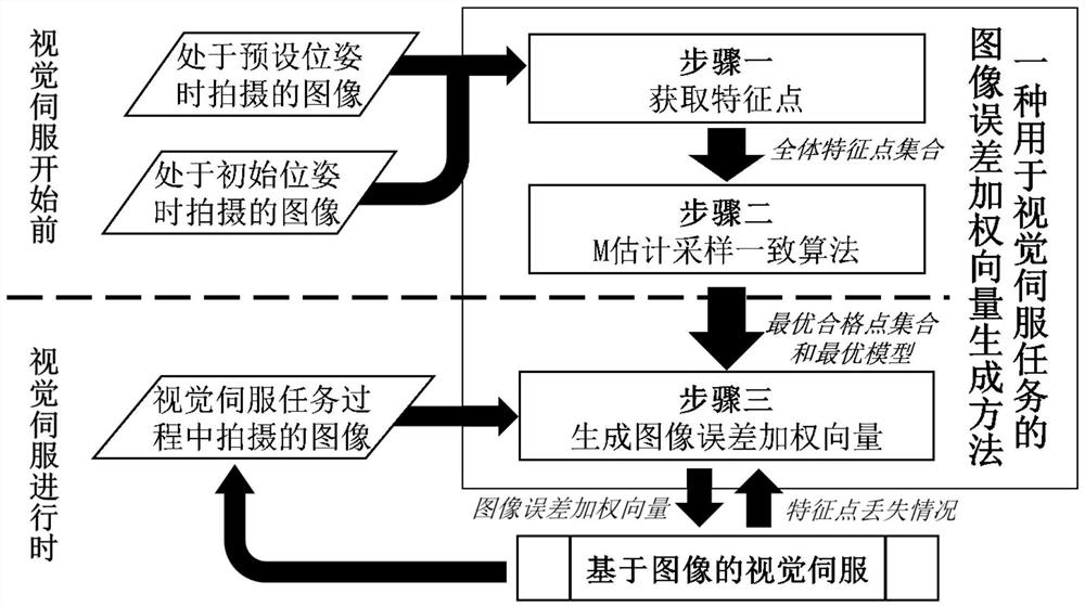
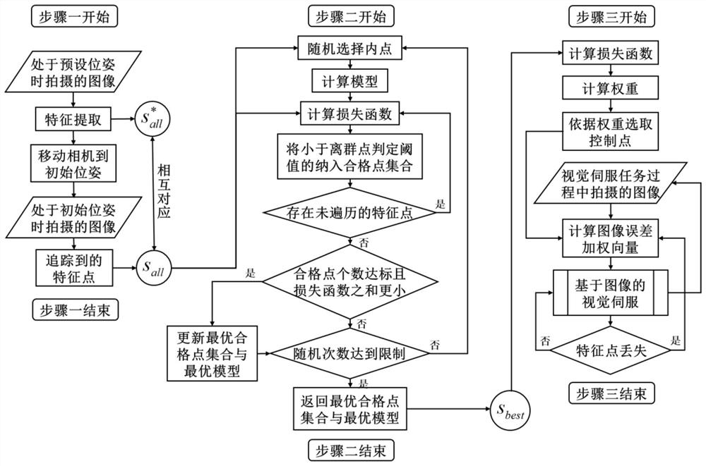
[0035] like figure 1 and 2 As shown, the present invention comprises the following steps:

[0036] Step 1: Obtain the target images taken when the camera in the visual servoing task is in the initial pose and the preset pose, respectively, and then use the feature extraction algorithm to extract the feature points of the target image when the camera is in the initial pose and the preset pose, respectively. Then, the initial and expected overall feature point sets are obtained respectively; the feature points in the initial and expected overall feature point sets are in one-to-one correspondence; feature extraction algorithms such as SIFT, SURF, ORB and other algorithms.

[0037] Step 2: According t...


PUM


Abstract

The invention discloses a visual servo method based on an image error weighted vector. Comprising the following steps: acquiring target images shot by a camera in a visual servo task when the camera is at an initial position and a preset position, respectively extracting image feature points by using a feature extraction algorithm, and respectively obtaining initial and expected all feature point sets; performing feature point screening on the initial all feature point set by using an M estimation sampling consensus algorithm to obtain an optimal qualified point set; the method comprises the following steps: firstly obtaining feature points of a target image, then endowing each feature point with different weights, then constructing initial and preset control point sets, then calculating an image error weighted vector, and performing visual servo on the target image based on the image error weighted vector. According to the method, the operand when a large number of image feature points are screened is reduced, the operand of a subsequent visual servo link is reduced by selecting a small number of high-quality feature points, meanwhile, lost control points are allowed to be replaced by other high-weight feature points when a visual servo task is carried out, and the quality of the control points is guaranteed.

Description

technical field [0001] The invention belongs to a visual servo method in the field of robot visual servo, and particularly relates to a visual servo method based on an image error weighted vector. Background technique [0002] With the complexity of robot tasks and the continuous development of machine vision technology, robot control methods relying on machine vision have been continuously proposed and improved, and the visual servo technology in the field of robot control has gradually formed, that is, the use of visual information to realize the autonomous movement of robots and Operation. Among the current visual servoing methods, there is a class of visual servoing that only relies on plane image data, which is called image-based visual servoing. In the image-based visual servoing task, it is necessary to extract feature points from the two-dimensional image space and select appropriate feature points as control points, and then calculate the image error weighting vect...

Claims


Application Information

Patent Timeline
Patent Type & Authority Applications(China)
IPC IPC(8): G06V10/771G06K9/62
CPCG06V10/771G06F18/2113
Inventor 聂勇董思旻黄方昊沈翀陈正唐建中
Owner ZHEJIANG UNIV
Learn More