Driving circuit

A driving circuit and driving chip technology, which is applied in the direction of electrical components, adjusting electrical variables, and high-efficiency power electronic conversion, can solve the problem that the switching loss and voltage stress of the switching tube Q1 cannot be taken into account at the same time, so as to improve work efficiency and reliability. The effect of increasing resistance and reducing switching loss

Pending Publication Date: 2022-08-02
浙江日风电气股份有限公司
View PDF0 Cites 0 Cited by
  • Summary
  • Abstract
  • Description
  • Claims
  • Application Information

AI Technical Summary

Problems solved by technology

At present, it is impossible to take into account the switching loss and voltage stress of the switching tube Q1 at the same time

Method used


Image

  • Driving circuit
  • Driving circuit
  • Driving circuit

Examples


Embodiment Construction

[0028] The technical solutions in the embodiments of the present application will be clearly and completely described below with reference to the drawings in the embodiments of the present application. Obviously, the described embodiments are only a part of the embodiments of the present application, but not all of the embodiments. All other embodiments obtained by those of ordinary skill in the art based on the embodiments in the present application without creative work fall within the protection scope of the present application.

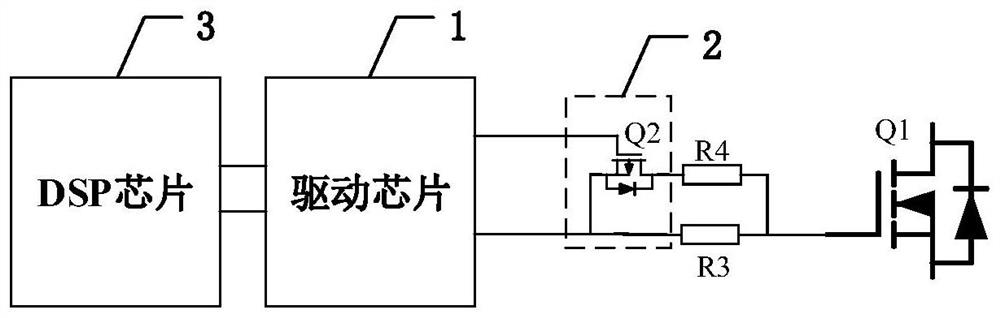
[0029] The core of the present application is to provide a driving circuit. When the driving chip receives a first control signal, it controls the switch unit to be turned on to ensure that the driving resistance is a second resistance with a low resistance value, thereby reducing the resistance value of the driving resistance to reduce the target switching losses of the switch. When the driving chip receives the second control signal, the switchi...


PUM


Abstract

The invention relates to the field of power electronics, and discloses a driving circuit which comprises a driving chip, a switch unit, a first resistor and a second resistor, the first output end of the driving chip is connected with the control end of a switch tube, the second output end of the driving chip is connected with the first connecting end of the switch tube, and the second connecting end of the switch tube is connected with one end of the second resistor. The common end, connected with one end of the first resistor, of the other end of the second resistor is connected with the target switch tube, the other end of the first resistor is connected with the first connecting end of the switch tube, and the resistance value of the first resistor is far larger than that of the second resistor. Therefore, when the driving chip receives the first control signal of the DSP chip, the switching unit is controlled to be switched on, and the driving resistor is the second resistor so as to reduce the switching loss of the target switching tube. And when the driving chip receives a second control signal of the DSP chip, the switch unit is controlled to be switched off, the driving resistor is the first resistor to reduce the voltage stress of the target switch tube, and the target switch tube is prevented from being damaged.

Description

technical field [0001] The present application relates to the field of power electronics, and in particular, to a drive circuit. Background technique [0002] With the continuous development of power electronic devices, power electronic technology is widely used in many new energy fields such as power supplies, inverters and frequency converters. The basic working principle of the power electronic topology is: control the high-frequency turn-on and turn-off of the switch tube through the drive circuit, and then realize the functions of voltage regulation, frequency regulation, rectification and inverter. It can be seen that the drive circuit is crucial to the normal operation of the entire circuit. [0003] The drive circuit usually consists of a drive chip and a drive resistor. figure 1 A structural diagram of a boost booster circuit provided by the present application, for example, taking the boost booster circuit as an example, such as figure 1 As shown, the boost volt...

Claims


Application Information

Patent Timeline
Patent Type & Authority Applications(China)
IPC IPC(8): H02M1/08H02M1/00H02M3/155
CPCH02M1/08H02M1/0054H02M3/155Y02B70/10
Inventor 陈建明朱成林柴克谦罗巍吴龙生卢钢
Owner 浙江日风电气股份有限公司
Why Eureka
Try Eureka