Automatic chip mounter

A placement machine and moving component technology, which is applied in the direction of electrical components, electrical components assembly of printed circuits, electrical components, etc., can solve the problem of easy wear of the belt drive, the placement accuracy cannot meet the requirements, and the number of feeder installations Less problems, to achieve the effect of improving work quality and work efficiency, reducing the distance of picking and placement, and shortening the working time

Pending Publication Date: 2022-08-02
封芳桂
View PDF0 Cites 1 Cited by
  • Summary
  • Abstract
  • Description
  • Claims
  • Application Information

AI Technical Summary

Problems solved by technology

[0004] The present invention proposes an automatic placement machine to solve the problem that the existing placement machine proposed in the above background technology is not suitable for the placement requirements of substrates with different sizes, and the belt-type transmission is prone to wear, breakage and slippage. Failure to meet requirements, high maintenance costs, and waste of space and efficiency caused by the small number of feeders installed under the same conditions

Method used


Image

  • Automatic chip mounter
  • Automatic chip mounter
  • Automatic chip mounter

Examples


Embodiment Construction

[0032] The technical solutions in the embodiments of the present invention will be clearly and completely described below with reference to the accompanying drawings in the embodiments of the present invention. Obviously, the described embodiments are only a part of the embodiments of the present invention, rather than all the embodiments. Based on the embodiments of the present invention, all other embodiments obtained by those of ordinary skill in the art without creative efforts shall fall within the protection scope of the present invention.

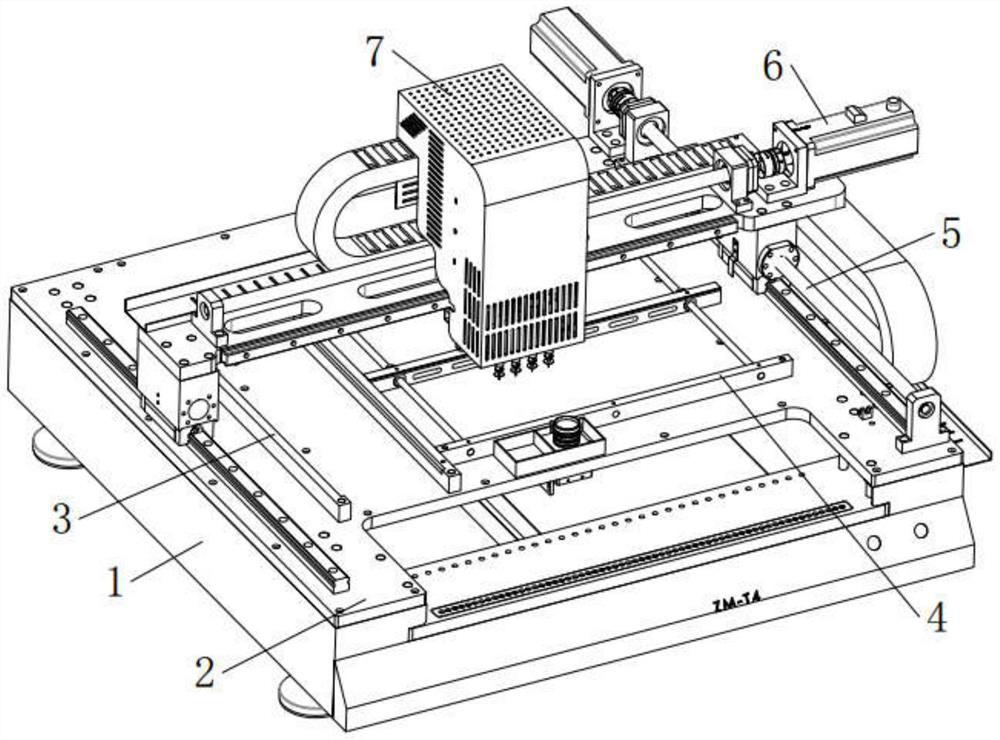
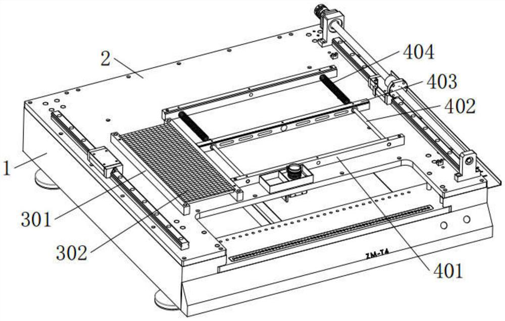
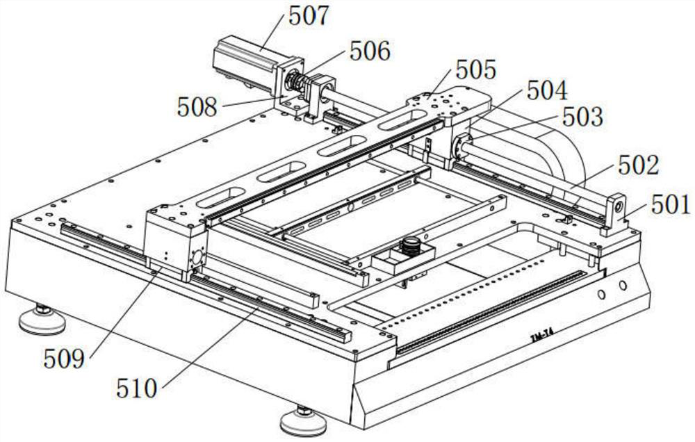
[0033] see Figure 1-Figure 6 , an automatic placement machine, comprising a bed 1, the upper surface of the bed 1 is fixedly mounted with a worktable 2, the middle area of ​​the upper surface of the worktable 2 is provided with a substrate placement area, the position of the substrate placement area A substrate positioning assembly 4 for clamping and positioning substrates of different sizes is installed there. The middle position ...


PUM


Abstract

An automatic chip mounter provided by the present invention comprises a lathe bed, the upper surface of the lathe bed is fixedly provided with a workbench, the middle area of the upper surface of the workbench is provided with a substrate placement area, and the substrate placement area is provided with a substrate positioning assembly used for clamping and positioning substrates of different sizes. The clamping and positioning assembly comprises base plate fixing blocks which are installed at the front end and the rear end of the upper surface of the workbench and are parallel to each other, and a base plate moving block which is parallel to the two base plate fixing blocks and moves front and back is arranged between the two base plate fixing blocks. The substrate placement area and the IC placement area are respectively arranged on the surface of the workbench, the material taking and surface mounting distance of the surface mounting head is effectively reduced, the working time is shortened, the substrate clamping distance is adjusted in the substrate placement area through the cooperation of the spring and the substrate movable block, the placement requirements of substrates of different sizes are met, and the application range is wide.

Description

technical field [0001] The invention relates to the technical field of placement machine design, in particular to an automatic placement machine. Background technique [0002] The placement machine, also known as the placement machine, is a special equipment for the placement of substrate components. It uses the control system placement head to walk in the working area, and completes the suction of the components from the feeder through the placement head suction nozzle. A small desktop placement equipment that can automatically identify the size deviation of components and correct the angle and position of component placement in real time through an automatic identification system (dual vision correction system). [0003] At present, the existing placement machines mainly have the following shortcomings: (1) Most of the substrate placement platforms in the working area of ​​the existing placement machines are of fixed size, or can only be adjusted slightly, which is not sui...

Claims


Application Information

Patent Timeline
Patent Type & Authority Applications(China)
IPC IPC(8): H05K3/30H05K13/00H05K13/04
CPCH05K3/303H05K13/00H05K13/0069H05K13/046
Inventor 许炉双封芳桂杨晓洹李文廷封芳宝胡龙生
Owner 封芳桂
Why Eureka
Try Eureka